
Page 159 - Optical Communications Essentials
P. 159
Passive Optical Components
Passive Optical Components 149
ting loss plus the excess loss in each path through the star. The splitting loss is given
in decibels by
1
Splitting loss =−10 log = 10 log N (9.5)
N
Similar to Eq. (9.2), for a single input power P in and N output powers, the excess loss
in decibels is given by
P
Fiber star excess loss = 10 log in (9.6)
N P
= i 1 out,i
The insertion loss and crosstalk can be found from Eqs. (9.3) and (9.4), respectively.
9.1.5. Mach-Zehnder interferometer
Wavelength-dependent multiplexers can be made by using Mach-Zehnder inter-
ferometry techniques. These devices can be either active or passive. Here we
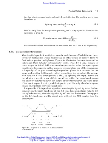
first look at passive multiplexers. Figure 9.4 illustrates the constituents of an
individual Mach-Zehnder interferometer (MZI). This 2 2 MZI consists of
three stages: an initial 3-dB directional coupler which splits the input signals
equally into two separate paths, a central section where one of the waveguides
is longer by ∆L to give a wavelength-dependent phase shift between the two
arms, and another 3-dB coupler which recombines the signals at the output.
The function of this arrangement is that, by splitting the input beams and
introducing a specific phase shift in one of the paths, the recombined signals
will interfere constructively at one output and destructively at the other. Thus,
if the input to port 1 is at λ 1 and the input to port 2 is at λ 2 , then both signals
finally emerge from only one output port.
Reciprocally, if independent signals at wavelengths λ 1 and λ 2 enter the bot-
tom port on the right-hand side of Fig. 9.4 (this time going from right to left
through the device), then the signal at λ 1 will exit the device from the top port
on the left-hand side, and the signal at λ 2 will exit the MZI coupler from the
bottom port.
Figure 9.4. Layout of a basic 2 2 Mach-Zehnder
interferometer.
Downloaded from Digital Engineering Library @ McGraw-Hill (www.digitalengineeringlibrary.com)
Copyright © 2004 The McGraw-Hill Companies. All rights reserved.
Any use is subject to the Terms of Use as given at the website.