
Page 179 - Optical Communications Essentials
P. 179
Active Optical Components
Active Optical Components 169
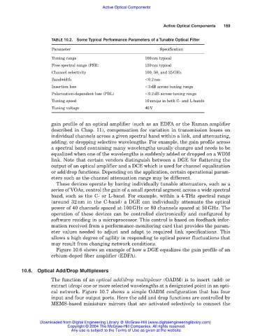
TABLE 10.2. Some Typical Performance Parameters of a Tunable Optical Filter
Parameter Specification
Tuning range 100nm typical
Free spectral range (FSR) 150nm typical
Channel selectivity 100, 50, and 25GHz
Bandwidth 0.2nm
Insertion loss 3dB across tuning range
Polarization-dependent loss (PDL) 0.2dB across tuning range
Tuning speed 10nm/µs in both C- and L-bands
Tuning voltage 40V
gain profile of an optical amplifier (such as an EDFA or the Raman amplifier
described in Chap. 11), compensation for variation in transmission losses on
individual channels across a given spectral band within a link, and attenuating,
adding, or dropping selective wavelengths. For example, the gain profile across
a spectral band containing many wavelengths usually changes and needs to be
equalized when one of the wavelengths is suddenly added or dropped on a WDM
link. Note that certain vendors distinguish between a DGE for flattening the
output of an optical amplifier and a DCE which is used for channel equalization
or add/drop functions. Depending on the application, certain operational param-
eters such as the channel attenuation range may be different.
These devices operate by having individually tunable attenuators, such as a
series of VOAs, control the gain of a small spectral segment across a wide spectral
band, such as the C- or L-band. For example, within a 4-THz spectral range
(around 32nm in the C-band) a DGE can individually attenuate the optical
power of 40 channels spaced at 100GHz or 80 channels spaced at 50GHz. The
operation of these devices can be controlled electronically and configured by
software residing in a microprocessor. This control is based on feedback infor-
mation received from a performance-monitoring card that provides the param-
eter values needed to adjust and adapt to required link specifications. This
allows a high degree of agility in responding to optical power fluctuations that
may result from changing network conditions.
Figure 10.6 shows an example of how a DGE equalizes the gain profile of an
erbium-doped fiber amplifier (EDFA).
10.6. Optical Add/Drop Multiplexers
The function of an optical add/drop multiplexer (OADM) is to insert (add) or
extract (drop) one or more selected wavelengths at a designated point in an opti-
cal network. Figure 10.7 shows a simple OADM configuration that has four
input and four output ports. Here the add and drop functions are controlled by
MEMS-based miniature mirrors that are activated selectively to connect the
Downloaded from Digital Engineering Library @ McGraw-Hill (www.digitalengineeringlibrary.com)
Copyright © 2004 The McGraw-Hill Companies. All rights reserved.
Any use is subject to the Terms of Use as given at the website.