
Page 239 - Optical Communications Essentials
P. 239
Constructing the WDM Network Puzzle
Constructing the WDM Network Puzzle 229
DWDM nodes
SONET/SDH
SONET/SDH
10-Gbps 10-Gbps 10-Gbps
IP IP
backbone backbone backbone
Gigabit Gigabit
Ethernet Ethernet
OADM
Metro
area
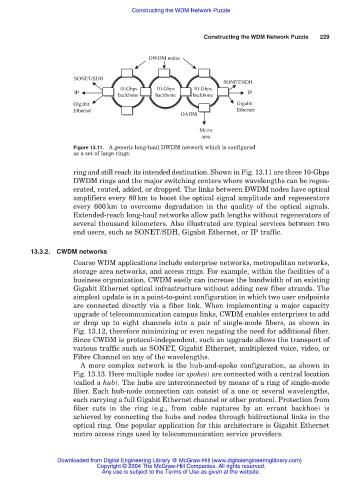
Figure 13.11. A generic long-haul DWDM network which is configured
as a set of large rings.
ring and still reach its intended destination. Shown in Fig. 13.11 are three 10-Gbps
DWDM rings and the major switching centers where wavelengths can be regen-
erated, routed, added, or dropped. The links between DWDM nodes have optical
amplifiers every 80km to boost the optical signal amplitude and regenerators
every 600km to overcome degradation in the quality of the optical signals.
Extended-reach long-haul networks allow path lengths without regenerators of
several thousand kilometers. Also illustrated are typical services between two
end users, such as SONET/SDH, Gigabit Ethernet, or IP traffic.
13.3.2. CWDM networks
Coarse WDM applications include enterprise networks, metropolitan networks,
storage area networks, and access rings. For example, within the facilities of a
business organization, CWDM easily can increase the bandwidth of an existing
Gigabit Ethernet optical infrastructure without adding new fiber strands. The
simplest update is in a point-to-point configuration in which two user endpoints
are connected directly via a fiber link. When implementing a major capacity
upgrade of telecommunication campus links, CWDM enables enterprises to add
or drop up to eight channels into a pair of single-mode fibers, as shown in
Fig. 13.12, therefore minimizing or even negating the need for additional fiber.
Since CWDM is protocol-independent, such an upgrade allows the transport of
various traffic such as SONET, Gigabit Ethernet, multiplexed voice, video, or
Fibre Channel on any of the wavelengths.
A more complex network is the hub-and-spoke configuration, as shown in
Fig. 13.13. Here multiple nodes (or spokes) are connected with a central location
(called a hub). The hubs are interconnected by means of a ring of single-mode
fiber. Each hub-node connection can consist of a one or several wavelengths,
each carrying a full Gigabit Ethernet channel or other protocol. Protection from
fiber cuts in the ring (e.g., from cable ruptures by an errant backhoe) is
achieved by connecting the hubs and nodes through bidirectional links in the
optical ring. One popular application for this architecture is Gigabit Ethernet
metro access rings used by telecommunication service providers.
Downloaded from Digital Engineering Library @ McGraw-Hill (www.digitalengineeringlibrary.com)
Copyright © 2004 The McGraw-Hill Companies. All rights reserved.
Any use is subject to the Terms of Use as given at the website.