
Page 234 - Optical Communications Essentials
P. 234
Constructing the WDM Network Puzzle
224 Chapter Thirteen
Laser VOAs Optical Passive
transmitters power multiplexer
monitors
TX1
TX1
TX2
TX2
Multiplexed
wavelengths
λ 1 through λ N
TXN
TXN
Control electronics
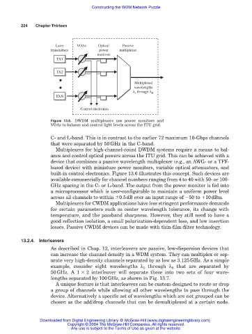
Figure 13.6. DWDM multiplexers use power monitors and
VOAs to balance and control light levels across the ITU grid.
C- and L-band. This is in contrast to the earlier 72 maximum 10-Gbps channels
that were separated by 50GHz in the C-band.
Multiplexers for high-channel-count DWDM systems require a means to bal-
ance and control optical powers across the ITU grid. This can be achieved with a
device that combines a passive wavelength multiplexer (e.g., an AWG- or a TFF-
based device) with miniature power monitors, variable optical attenuators, and
built-in control electronics. Figure 13.6 illustrates this concept. Such devices are
available commercially for channel numbers ranging from 4 to 40 with 50- or 100-
GHz spacing in the C- or L-band. The output from the power monitor is fed into
a microprocessor which is user-configurable to maintain a uniform power level
across all channels to within 0.5dB over an input range of 50 to 10dBm.
Multiplexers for CWDM applications have less stringent performance demands
for certain parameters such as center wavelength tolerance, its change with
temperature, and the passband sharpness. However, they still need to have a
good reflection isolation, a small polarization-dependent loss, and low insertion
losses. Passive CWDM devices can be made with thin-film-filter technology.
13.2.4. Interleavers
As described in Chap. 12, interleavers are passive, low-dispersion devices that
can increase the channel density in a WDM system. They can multiplex or sep-
arate very high-density channels separated by as low as 3.125GHz. As a simple
example, consider eight wavelengths λ 1 through λ 8 that are separated by
50GHz. A 1 2 interleaver will separate these into two sets of four wave-
lengths separated by 100GHz, as shown in Fig. 13.7.
A unique feature is that interleavers can be custom-designed to route or drop
a group of channels while allowing all other wavelengths to pass through the
device. Alternatively a specific set of wavelengths which are not grouped can be
chosen as the add/drop channels that can be demultiplexed at a certain node.
Downloaded from Digital Engineering Library @ McGraw-Hill (www.digitalengineeringlibrary.com)
Copyright © 2004 The McGraw-Hill Companies. All rights reserved.
Any use is subject to the Terms of Use as given at the website.