
Page 286 - Optical Communications Essentials
P. 286
Optical Link Design
276 Chapter Sixteen
■ To maintain a proper spacing between pulses
■ To indicate the start and end of each timing interval
In addition, since errors resulting from channel noise and distortion mech-
anisms can occur in the signal detection process, it may be desirable for the sig-
nal to have an inherent error-detecting capability as well as an error correction
mechanism if it is needed or is practical. These features can be incorporated
into the data stream by structuring or encoding the signal. Generally one does
this by introducing extra bits into the raw data stream at the transmitter on a
regular and logical basis and extracting them again at the receiver. This process
is called channel coding or line coding. This section presents some examples of
generic encoding techniques.
16.4.1. NRZ and RZ signal formats
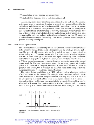
The simplest method for encoding data is the unipolar non-return-to-zero (NRZ)
code. Unipolar means that a logic 1 is represented by a voltage or light pulse
that fills an entire bit period, whereas for a logic 0 no pulse is transmitted, as
shown in Fig. 16.7. The coded patterns in this figure are for the data sequence
1010110. If 1 and 0 voltage pulses occur with equal probability and if the ampli-
tude of the voltage pulse is A, then the average transmitted power for this code
2
is A /2. In optical systems one typically describes a pulse in terms of its optical
power level. In this case the average power for an equal number of 1 and 0
pulses is P/2, where P is the peak power in a 1 pulse. An NRZ code is simple to
generate and decode, but it possesses no inherent error monitoring or correct-
ing capabilities and it contains no timing features.
The lack of timing capabilities in an NRZ code can lead to misinterpretations
of the bit stream at the receiver. For example, since there are no level transi-
tions from which to extract timing information in a long sequence of NRZ 1s or
0s, a long string of N identical bits could be interpreted as either N 1 or N 1
bits, unless highly stable (and expensive) clocks are used. This problem can be
alleviated with a code that has transitions at the beginning of each bit interval
when a binary 1 is transmitted and no transition for a binary 0. This can be
1 0 1 0 1 1 0
NRZ A
0
RZ A
0
Figure 16.7. NRZ and RZ code patterns for the data sequence
1010110.
Downloaded from Digital Engineering Library @ McGraw-Hill (www.digitalengineeringlibrary.com)
Copyright © 2004 The McGraw-Hill Companies. All rights reserved.
Any use is subject to the Terms of Use as given at the website.