
Page 281 - Optical Communications Essentials
P. 281
Optical Link Design
Optical Link Design 271
Laser WDM EDFA WDM Optical Optical
transmitters mux (gain = 20 dB) demux filters receivers
• •
• OADM •
OADM
GFF
24-km 24-km GFF 60-km
fiber fiber fiber
Added/dropped
wavelengths 1-dB
P S P R
loss
3 dB 6 dB 4 dB 6 dB 3 dB 15 dB 3 dB 3 dB
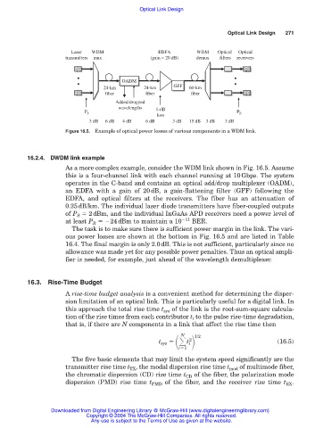
Figure 16.5. Example of optical power losses of various components in a WDM link.
16.2.4. DWDM link example
As a more complex example, consider the WDM link shown in Fig. 16.5. Assume
this is a four-channel link with each channel running at 10Gbps. The system
operates in the C-band and contains an optical add/drop multiplexer (OADM),
an EDFA with a gain of 20dB, a gain-flattening filter (GFF) following the
EDFA, and optical filters at the receivers. The fiber has an attenuation of
0.25dB/km. The individual laser diode transmitters have fiber-coupled outputs
of P S 2dBm, and the individual InGaAs APD receivers need a power level of
at least P R 24dBm to maintain a 10 11 BER.
The task is to make sure there is sufficient power margin in the link. The vari-
ous power losses are shown at the bottom in Fig. 16.5 and are listed in Table
16.4. The final margin is only 2.0dB. This is not sufficient, particularly since no
allowance was made yet for any possible power penalties. Thus an optical ampli-
fier is needed, for example, just ahead of the wavelength demultiplexer.
16.3. Rise-Time Budget
A rise-time budget analysis is a convenient method for determining the disper-
sion limitation of an optical link. This is particularly useful for a digital link. In
this approach the total rise time t sys of the link is the root-sum-square calcula-
tion of the rise times from each contributor t i to the pulse rise-time degradation,
that is, if there are N components in a link that affect the rise time then
N 2 1/2
t sys i (16.5)
t
i 1
The five basic elements that may limit the system speed significantly are the
transmitter rise time t TX , the modal dispersion rise time t mod of multimode fiber,
the chromatic dispersion (CD) rise time t CD of the fiber, the polarization mode
dispersion (PMD) rise time t PMD of the fiber, and the receiver rise time t RX .
Downloaded from Digital Engineering Library @ McGraw-Hill (www.digitalengineeringlibrary.com)
Copyright © 2004 The McGraw-Hill Companies. All rights reserved.
Any use is subject to the Terms of Use as given at the website.