
Page 280 - Optical Communications Essentials
P. 280
Optical Link Design
270 Chapter Sixteen
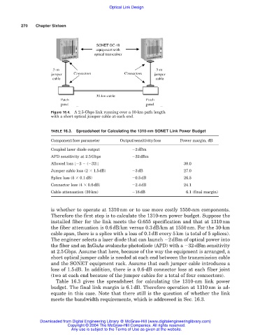
Figure 16.4. A 2.5-Gbps link running over a 30-km path length
with a short optical jumper cable at each end.
TABLE 16.3. Spreadsheet for Calculating the 1310-nm SONET Link Power Budget
Component/loss parameter Output/sensitivity/loss Power margin, dB
Coupled laser diode output 2dBm
APD sensitivity at 2.5Gbps 32dBm
Allowed loss [ 2 ( 32)] 30.0
Jumper cable loss (2 1.5dB) 3dB 27.0
Splice loss (5 0.1dB) 0.5dB 26.5
Connector loss (4 0.6dB) 2.4dB 24.1
Cable attenuation (30km) 18dB 6.1 (final margin)
is whether to operate at 1310nm or to use more costly 1550-nm components.
Therefore the first step is to calculate the 1310-nm power budget. Suppose the
installed fiber for the link meets the G.655 specification and that at 1310nm
the fiber attenuation is 0.6dB/km versus 0.3dB/km at 1550nm. For the 30-km
cable span, there is a splice with a loss of 0.1dB every 5km (a total of 5 splices).
The engineer selects a laser diode that can launch 2dBm of optical power into
the fiber and an InGaAs avalanche photodiode (APD) with a 32-dBm sensitivity
at 2.5Gbps. Assume that here, because of the way the equipment is arranged, a
short optical jumper cable is needed at each end between the transmission cable
and the SONET equipment rack. Assume that each jumper cable introduces a
loss of 1.5dB. In addition, there is a 0.6-dB connector loss at each fiber joint
(two at each end because of the jumper cables for a total of four connectors).
Table 16.3 gives the spreadsheet for calculating the 1310-nm link power
budget. The final link margin is 6.1dB. Therefore operation at 1310nm is ad-
equate in this case. Note that there still is the question of whether the link
meets the bandwidth requirements, which is addressed in Sec. 16.3.
Downloaded from Digital Engineering Library @ McGraw-Hill (www.digitalengineeringlibrary.com)
Copyright © 2004 The McGraw-Hill Companies. All rights reserved.
Any use is subject to the Terms of Use as given at the website.