
Page 279 - Optical Communications Essentials
P. 279
Optical Link Design
Optical Link Design 269
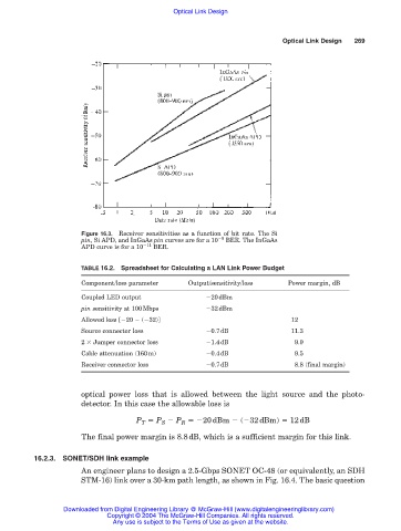
Figure 16.3. Receiver sensitivities as a function of bit rate. The Si
pin, Si APD, and InGaAs pin curves are for a 10 9 BER. The InGaAs
APD curve is for a 10 11 BER.
TABLE 16.2. Spreadsheet for Calculating a LAN Link Power Budget
Component/loss parameter Output/sensitivity/loss Power margin, dB
Coupled LED output 20dBm
pin sensitivity at 100Mbps 32dBm
Allowed loss [ 20 ( 32)] 12
Source connector loss 0.7dB 11.3
2 Jumper connector loss 1.4dB 9.9
Cable attenuation (160m) 0.4dB 9.5
Receiver connector loss 0.7dB 8.8 (final margin)
optical power loss that is allowed between the light source and the photo-
detector. In this case the allowable loss is
P T P S P R 20dBm ( 32dBm) 12dB
The final power margin is 8.8dB, which is a sufficient margin for this link.
16.2.3. SONET/SDH link example
An engineer plans to design a 2.5-Gbps SONET OC-48 (or equivalently, an SDH
STM-16) link over a 30-km path length, as shown in Fig. 16.4. The basic question
Downloaded from Digital Engineering Library @ McGraw-Hill (www.digitalengineeringlibrary.com)
Copyright © 2004 The McGraw-Hill Companies. All rights reserved.
Any use is subject to the Terms of Use as given at the website.