Page 305 - Optical Communications Essentials
P. 305

Optical Networks


                                                                           Optical Networks  295


                                                   Primary 2-fiber
                                                   bidirectional loop
                                     4p
                                                                   1p
                                           Node
                                     8p                        5p
                             4s              1
                                                               1s
                             8s                             5s
                                   Secondary 2-fiber
                                   bidirectional protection loop
                        Node                                   Node
                         4                                      2


                                                                6p  2p
                                  7s                  6s
                         7p        3s      Node       2s
                                             3
                      3p
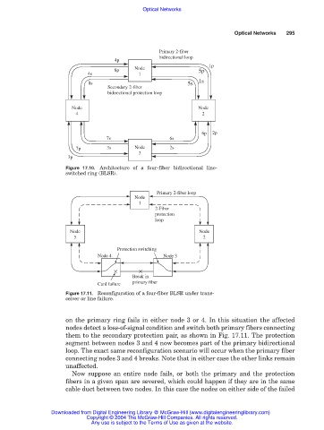
                      Figure 17.10. Architecture of a four-fiber bidirectional line-
                      switched ring (BLSR).

                                                  Primary 2-fiber loop
                                           Node
                                             1
                                                  2-Fiber
                                                  protection
                                                  loop
                       Node                                     Node
                        5                                        2
                                      Protection switching
                                Node 4              Node 3


                                           Break in
                                Card failure  primary fiber
                      Figure 17.11. Reconfiguration of a four-fiber BLSR under trans-
                      ceiver or line failure.


                      on the primary ring fails in either node 3 or 4. In this situation the affected
                      nodes detect a loss-of-signal condition and switch both primary fibers connecting
                      them to the secondary protection pair, as shown in Fig. 17.11. The protection
                      segment between nodes 3 and 4 now becomes part of the primary bidirectional
                      loop. The exact same reconfiguration scenario will occur when the primary fiber
                      connecting nodes 3 and 4 breaks. Note that in either case the other links remain
                      unaffected.
                        Now suppose an entire node fails, or both the primary and the protection
                      fibers in a given span are severed, which could happen if they are in the same
                      cable duct between two nodes. In this case the nodes on either side of the failed


                 Downloaded from Digital Engineering Library @ McGraw-Hill (www.digitalengineeringlibrary.com)
                            Copyright © 2004 The McGraw-Hill Companies. All rights reserved.
                              Any use is subject to the Terms of Use as given at the website.
   300   301   302   303   304   305   306   307   308   309   310