
Page 301 - Optical Communications Essentials
P. 301
Optical Networks
Optical Networks 291
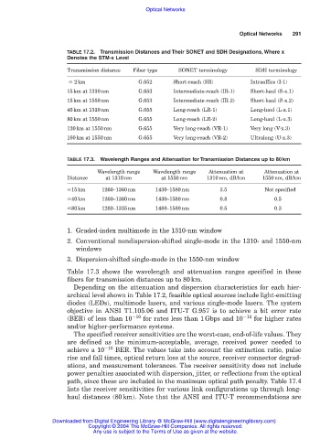
TABLE 17.2. Transmission Distances and Their SONET and SDH Designations, Where x
Denotes the STM-x Level
Transmission distance Fiber type SONET terminology SDH terminology
2km G.652 Short-reach (SR) Intraoffice (I-1)
15km at 1310nm G.653 Intermediate-reach (IR-1) Short-haul (S-x.1)
15km at 1550nm G.653 Intermediate-reach (IR-2) Short-haul (S-x.2)
40km at 1310nm G.655 Long-reach (LR-1) Long-haul (L-x.1)
80km at 1550nm G.655 Long-reach (LR-2) Long-haul (L-x.3)
120km at 1550nm G.655 Very long-reach (VR-1) Very long (V-x.3)
160km at 1550nm G.655 Very long-reach (VR-2) Ultralong (U-x.3)
TABLE 17.3. Wavelength Ranges and Attenuation for Transmission Distances up to 80km
Wavelength range Wavelength range Attenuation at Attenuation at
Distance at 1310nm at 1550nm 1310nm, dB/km 1550nm, dB/km
15km 1260–1360nm 1430–1580nm 3.5 Not specified
40km 1260–1360nm 1430–1580nm 0.8 0.5
80km 1280–1335nm 1480–1580nm 0.5 0.3
1. Graded-index multimode in the 1310-nm window
2. Conventional nondispersion-shifted single-mode in the 1310- and 1550-nm
windows
3. Dispersion-shifted single-mode in the 1550-nm window
Table 17.3 shows the wavelength and attenuation ranges specified in these
fibers for transmission distances up to 80km.
Depending on the attenuation and dispersion characteristics for each hier-
archical level shown in Table 17.2, feasible optical sources include light-emitting
diodes (LEDs), multimode lasers, and various single-mode lasers. The system
objective in ANSI T1.105.06 and ITU-T G.957 is to achieve a bit error rate
(BER) of less than 10 10 for rates less than 1Gbps and 10 12 for higher rates
and/or higher-performance systems.
The specified receiver sensitivities are the worst-case, end-of-life values. They
are defined as the minimum-acceptable, average, received power needed to
achieve a 10 10 BER. The values take into account the extinction ratio, pulse
rise and fall times, optical return loss at the source, receiver connector degrad-
ations, and measurement tolerances. The receiver sensitivity does not include
power penalties associated with dispersion, jitter, or reflections from the optical
path, since these are included in the maximum optical path penalty. Table 17.4
lists the receiver sensitivities for various link configurations up through long-
haul distances (80km). Note that the ANSI and ITU-T recommendations are
Downloaded from Digital Engineering Library @ McGraw-Hill (www.digitalengineeringlibrary.com)
Copyright © 2004 The McGraw-Hill Companies. All rights reserved.
Any use is subject to the Terms of Use as given at the website.