
Page 334 - Optical Communications Essentials
P. 334
Test and Measurement
324 Chapter Nineteen
19.2. Basic Test Equipment
As optical signals pass through the various parts of an optical link, they need to
be measured and characterized in terms of the three fundamental areas of optic-
al power, polarization, and spectral content. The basic pieces of test equipment
for carrying out such measurements on optical fiber components and systems
include optical power meters, attenuators, tunable laser sources, spectrum ana-
lyzers, and time-domain reflectometers. These come in a variety of capabilities,
with sizes ranging from portable, handheld units for field use to sophisticated
briefcase-size bench-top or rack-mountable instruments for laboratory and
manufacturing applications. In general, the field units do not need to have the
extremely high precision of laboratory instruments, but they need to be more
rugged to maintain reliable and accurate measurements under extreme envir-
onmental conditions of temperature, humidity, dust, and mechanical stress.
However, even the handheld equipment for field use has reached a high degree
of sophistication with automated microprocessor-controlled test features and
computer interface capabilities.
More sophisticated instruments, such as polarization analyzers and optical
communication analyzers, are available for measuring and analyzing polariza-
tion mode dispersion (PMD), eye diagrams, and pulse waveforms. These instru-
ments enable a variety of statistical measurements to be made at the push of a
button, after the user has keyed in the parameters to be tested and the desired
measurement range.
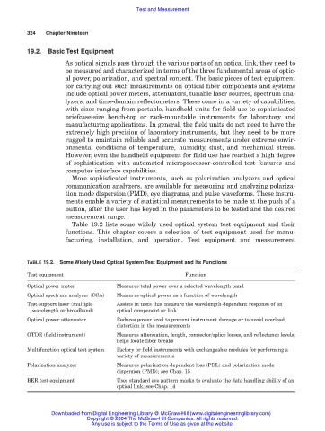
Table 19.2 lists some widely used optical system test equipment and their
functions. This chapter covers a selection of test equipment used for manu-
facturing, installation, and operation. Test equipment and measurement
TABLE 19.2. Some Widely Used Optical System Test Equipment and Its Functions
Test equipment Function
Optical power meter Measures total power over a selected wavelength band
Optical spectrum analyzer (OSA) Measures optical power as a function of wavelength
Test-support laser (multiple- Assists in tests that measure the wavelength-dependent response of an
wavelength or broadband) optical component or link
Optical power attenuator Reduces power level to prevent instrument damage or to avoid overload
distortion in the measurements
OTDR (field instrument) Measures attenuation, length, connector/splice losses, and reflectance levels;
helps locate fiber breaks
Multifunction optical test system Factory or field instruments with exchangeable modules for performing a
variety of measurements
Polarization analyzer Measures polarization-dependent loss (PDL) and polarization mode
dispersion (PMD); see Chap. 15
BER test equipment Uses standard eye pattern masks to evaluate the data handling ability of an
optical link; see Chap. 14
Downloaded from Digital Engineering Library @ McGraw-Hill (www.digitalengineeringlibrary.com)
Copyright © 2004 The McGraw-Hill Companies. All rights reserved.
Any use is subject to the Terms of Use as given at the website.