
Page 58 - Optical Communications Essentials
P. 58
Optical Fibers
48 Chapter Four
Figure 4.1. End-face cross section and a longitudinal cross
section of a standard optical fiber.
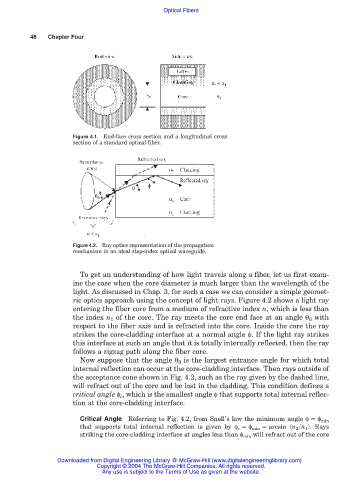
Figure 4.2. Ray optics representation of the propagation
mechanism in an ideal step-index optical waveguide.
To get an understanding of how light travels along a fiber, let us first exam-
ine the case when the core diameter is much larger than the wavelength of the
light. As discussed in Chap. 3, for such a case we can consider a simple geomet-
ric optics approach using the concept of light rays. Figure 4.2 shows a light ray
entering the fiber core from a medium of refractive index n, which is less than
the index n 1 of the core. The ray meets the core end face at an angle θ 0 with
respect to the fiber axis and is refracted into the core. Inside the core the ray
strikes the core-cladding interface at a normal angle φ. If the light ray strikes
this interface at such an angle that it is totally internally reflected, then the ray
follows a zigzag path along the fiber core.
Now suppose that the angle θ 0 is the largest entrance angle for which total
internal reflection can occur at the core-cladding interface. Then rays outside of
the acceptance cone shown in Fig. 4.2, such as the ray given by the dashed line,
will refract out of the core and be lost in the cladding. This condition defines a
critical angle φ c , which is the smallest angle φ that supports total internal reflec-
tion at the core-cladding interface.
Critical Angle Referring to Fig. 4.2, from Snell’s law the minimum angle φ φ min
that supports total internal reflection is given by φ c φ min arcsin (n 2 /n 1 ). Rays
striking the core-cladding interface at angles less than φ min will refract out of the core
Downloaded from Digital Engineering Library @ McGraw-Hill (www.digitalengineeringlibrary.com)
Copyright © 2004 The McGraw-Hill Companies. All rights reserved.
Any use is subject to the Terms of Use as given at the website.