
Page 61 - Optical Communications Essentials
P. 61
Optical Fibers
Optical Fibers 51
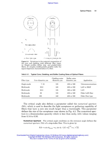
Figure 4.4. Variations in the material composition of
the core and cladding yield different fiber types.
(a) Simple profiles define step- and graded-index
fibers; (b) complex cladding-index profiles tailor the
signal dispersion characteristics of a fiber.
TABLE 4.1. Typical Core, Cladding, and Buffer Coating Sizes of Optical Fibers
Cladding outer Buffer outer
Fiber type Core diameter, µm diameter, µm diameter, µm Application
Single-mode 7–10 125 250 or 500 Telecommunications
Multimode 50.0 125 250 or 500 LAN or MAN
Multimode 62.5 125 250 or 500 LAN
Multimode 85 125 250 or 500 Older LAN fiber
Multimode 100 140 250 or 500 Older fiber type
The critical angle also defines a parameter called the numerical aperture
(NA), which is used to describe the light acceptance or gathering capability of
fibers that have a core size much larger than a wavelength. This parameter
defines the size of the acceptance cone shown in Fig. 4.2. The numerical aper-
ture is a dimensionless quantity which is less than unity, with values ranging
from 0.14 to 0.50.
Numerical Aperture The critical angle condition on the entrance angle defines the
numerical aperture (NA) of a step-index fiber. This is given by
1/2
NA n sin θ 0,max n 1 sin θ c n 1 n 2 ≈n 1 2 ∆
2
2
Downloaded from Digital Engineering Library @ McGraw-Hill (www.digitalengineeringlibrary.com)
Copyright © 2004 The McGraw-Hill Companies. All rights reserved.
Any use is subject to the Terms of Use as given at the website.