
Page 66 - Optical Communications Essentials
P. 66
Optical Fibers
56 Chapter Four
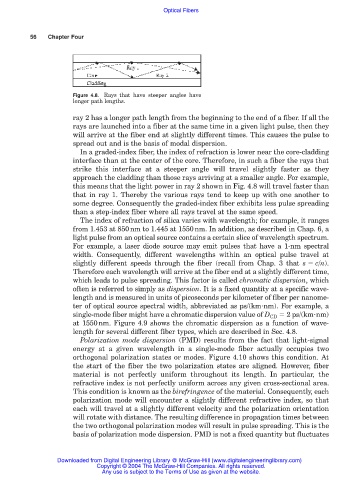
Figure 4.8. Rays that have steeper angles have
longer path lengths.
ray 2 has a longer path length from the beginning to the end of a fiber. If all the
rays are launched into a fiber at the same time in a given light pulse, then they
will arrive at the fiber end at slightly different times. This causes the pulse to
spread out and is the basis of modal dispersion.
In a graded-index fiber, the index of refraction is lower near the core-cladding
interface than at the center of the core. Therefore, in such a fiber the rays that
strike this interface at a steeper angle will travel slightly faster as they
approach the cladding than those rays arriving at a smaller angle. For example,
this means that the light power in ray 2 shown in Fig. 4.8 will travel faster than
that in ray 1. Thereby the various rays tend to keep up with one another to
some degree. Consequently the graded-index fiber exhibits less pulse spreading
than a step-index fiber where all rays travel at the same speed.
The index of refraction of silica varies with wavelength; for example, it ranges
from 1.453 at 850nm to 1.445 at 1550nm. In addition, as described in Chap. 6, a
light pulse from an optical source contains a certain slice of wavelength spectrum.
For example, a laser diode source may emit pulses that have a 1-nm spectral
width. Consequently, different wavelengths within an optical pulse travel at
slightly different speeds through the fiber (recall from Chap. 3 that s c/n).
Therefore each wavelength will arrive at the fiber end at a slightly different time,
which leads to pulse spreading. This factor is called chromatic dispersion, which
often is referred to simply as dispersion. It is a fixed quantity at a specific wave-
length and is measured in units of picoseconds per kilometer of fiber per nanome-
ter of optical source spectral width, abbreviated as ps/(km nm). For example, a
single-mode fiber might have a chromatic dispersion value of D CD 2 ps/(km nm)
at 1550nm. Figure 4.9 shows the chromatic dispersion as a function of wave-
length for several different fiber types, which are described in Sec. 4.8.
Polarization mode dispersion (PMD) results from the fact that light-signal
energy at a given wavelength in a single-mode fiber actually occupies two
orthogonal polarization states or modes. Figure 4.10 shows this condition. At
the start of the fiber the two polarization states are aligned. However, fiber
material is not perfectly uniform throughout its length. In particular, the
refractive index is not perfectly uniform across any given cross-sectional area.
This condition is known as the birefringence of the material. Consequently, each
polarization mode will encounter a slightly different refractive index, so that
each will travel at a slightly different velocity and the polarization orientation
will rotate with distance. The resulting difference in propagation times between
the two orthogonal polarization modes will result in pulse spreading. This is the
basis of polarization mode dispersion. PMD is not a fixed quantity but fluctuates
Downloaded from Digital Engineering Library @ McGraw-Hill (www.digitalengineeringlibrary.com)
Copyright © 2004 The McGraw-Hill Companies. All rights reserved.
Any use is subject to the Terms of Use as given at the website.