
Page 64 - Optical Communications Essentials
P. 64
Optical Fibers
54 Chapter Four
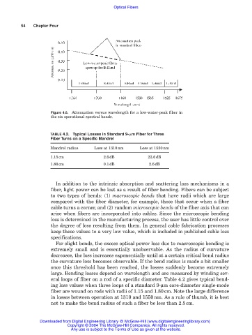
Figure 4.6. Attenuation versus wavelength for a low-water-peak fiber in
the six operational spectral bands.
TABLE 4.2. Typical Losses in Standard 9- m Fiber for Three
Fiber Turns on a Specific Mandrel
Mandrel radius Loss at 1310nm Loss at 1550nm
1.15cm 2.6dB 23.6dB
1.80cm 0.1dB 2.6dB
In addition to the intrinsic absorption and scattering loss mechanisms in a
fiber, light power can be lost as a result of fiber bending. Fibers can be subject
to two types of bends: (1) macroscopic bends that have radii which are large
compared with the fiber diameter, for example, those that occur when a fiber
cable turns a corner, and (2) random microscopic bends of the fiber axis that can
arise when fibers are incorporated into cables. Since the microscopic bending
loss is determined in the manufacturing process, the user has little control over
the degree of loss resulting from them. In general cable fabrication processes
keep these values to a very low value, which is included in published cable loss
specifications.
For slight bends, the excess optical power loss due to macroscopic bending is
extremely small and is essentially unobservable. As the radius of curvature
decreases, the loss increases exponentially until at a certain critical bend radius
the curvature loss becomes observable. If the bend radius is made a bit smaller
once this threshold has been reached, the losses suddenly become extremely
large. Bending losses depend on wavelength and are measured by winding sev-
eral loops of fiber on a rod of a specific diameter. Table 4.2 gives typical bend-
ing loss values when three loops of a standard 9-µm core-diameter single-mode
fiber are wound on rods with radii of 1.15 and 1.80cm. Note the large difference
in losses between operation at 1310 and 1550nm. As a rule of thumb, it is best
not to make the bend radius of such a fiber be less than 2.5cm.
Downloaded from Digital Engineering Library @ McGraw-Hill (www.digitalengineeringlibrary.com)
Copyright © 2004 The McGraw-Hill Companies. All rights reserved.
Any use is subject to the Terms of Use as given at the website.