
Page 86 - Optical Communications Essentials
P. 86
Optical Fiber Cables
76 Chapter Five
internal strength member that allows the cable to be strung between poles
without implementing any additional support to the cable. For the facility-sup-
porting cable, first a separate wire or strength member is strung between the
poles, and then the cable is lashed or clipped to this member. Three common
self-supporting aerial cable structures known as OPGW, ADSS, and figure 8 are
described below.
In addition to housing the optical fibers, the optical ground wire (OPGW)
cable structure contains a steel or aluminum tube that is designed to carry the
ground current of an electrical system. The metal structure acts as the strength
member of the cable. OPGW cables with up to 144 fibers are available.
The all-dielectric self-supporting (ADSS) cable uses only dielectric materials,
such as aramid yarns and glass-reinforced polymers, for strength and protection
of the fibers. An ADSS cable typically contains 288 fibers in a loose-tube
stranded-cable-core structure.
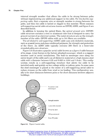
Figure 5.8 illustrates a popular aerial cable known as a figure 8 cable because
of its shape. A key feature is the factory-attached messenger, which is a support
member used in aerial installations. The built-in messenger runs along the
entire length of the cable and is an all-dielectric material or a high-tension steel
cable with a diameter between 0.25 and 0.625 in (0.64 and 1.6cm). This config-
uration results in a self-supporting structure that allows the cable to be
installed easily and quickly on low-voltage utility or railway poles. In some cases
the steel messenger is placed at the center of a self-supporting aerial cable to
reduce stresses on the cable from wind or ice loading. This configuration usu-
ally is for short distances between poles or for short distances between adjacent
buildings.
Figure 5.8. Figure 8 aerial cable.
Downloaded from Digital Engineering Library @ McGraw-Hill (www.digitalengineeringlibrary.com)
Copyright © 2004 The McGraw-Hill Companies. All rights reserved.
Any use is subject to the Terms of Use as given at the website.