
Page 81 - Optical Communications Essentials
P. 81
Optical Fiber Cables
Optical Fiber Cables 71
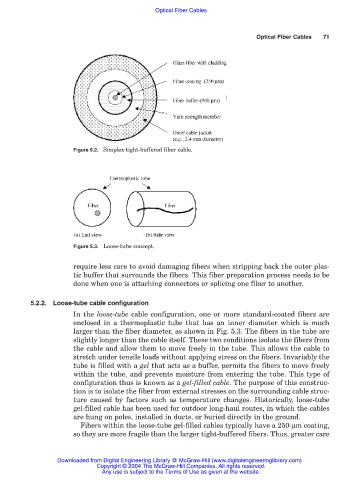
Figure 5.2. Simplex tight-buffered fiber cable.
Figure 5.3. Loose-tube concept.
require less care to avoid damaging fibers when stripping back the outer plas-
tic buffer that surrounds the fibers. This fiber preparation process needs to be
done when one is attaching connectors or splicing one fiber to another.
5.2.2. Loose-tube cable configuration
In the loose-tube cable configuration, one or more standard-coated fibers are
enclosed in a thermoplastic tube that has an inner diameter which is much
larger than the fiber diameter, as shown in Fig. 5.3. The fibers in the tube are
slightly longer than the cable itself. These two conditions isolate the fibers from
the cable and allow them to move freely in the tube. This allows the cable to
stretch under tensile loads without applying stress on the fibers. Invariably the
tube is filled with a gel that acts as a buffer, permits the fibers to move freely
within the tube, and prevents moisture from entering the tube. This type of
configuration thus is known as a gel-filled cable. The purpose of this construc-
tion is to isolate the fiber from external stresses on the surrounding cable struc-
ture caused by factors such as temperature changes. Historically, loose-tube
gel-filled cable has been used for outdoor long-haul routes, in which the cables
are hung on poles, installed in ducts, or buried directly in the ground.
Fibers within the loose-tube gel-filled cables typically have a 250-µm coating,
so they are more fragile than the larger tight-buffered fibers. Thus, greater care
Downloaded from Digital Engineering Library @ McGraw-Hill (www.digitalengineeringlibrary.com)
Copyright © 2004 The McGraw-Hill Companies. All rights reserved.
Any use is subject to the Terms of Use as given at the website.