
Page 91 - Optical Communications Essentials
P. 91
Optical Fiber Cables
Optical Fiber Cables 81
Trenching is more time-consuming than direct plowing since it requires a
trench to be dug by hand or by machine to some specified depth. However,
trenching allows the installation to be more controlled than in plowing. For
example, in direct plowing it is not known if a sharp rock is left pressing against
the installed cable or if the cable was damaged in some way that may cause it
to fail later.
Usually a combination of the two methods is used, with plowing being done in
isolated open areas and trenching being done where plowing is not possible, such
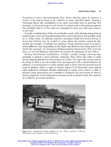
as in urban areas. In addition, another technique called directional boring or
horizontal drilling may be needed in areas where the surface cannot be dis-
turbed, for example, a multiple-lane highway. These machines come in at least a
dozen different sizes depending on the depth and distance that holes need to be
bored. For example, the horizontal drilling machine illustrated in Fig. 5.13 can
bore a 3- to 8-cm-diameter hole below the surface for distances of over 100m.
During direct-burial installations, a bright (usually orange) warning tape
normally is placed a short distance (typically 18in) above the cable to alert
future digging operators to the presence of a cable. The tape may contain metal-
lic strips so that it can be located from aboveground with a metal detector. In
addition, a warning post or a cable marker that is flush with the ground may be
used to indicate where a cable is buried. Figure 5.14 illustrates some typical
cable indication methods. Besides indicating to repair crews where a cable is
located, these precautions are intended to minimize the occurrence of what is
known popularly in the telecommunications world as backhoe fade (the rupture
of a cable by an errant backhoe).
Figure 5.13. Directional boring machine in use. (Photo courtesy of Vermeer
Manufacturing Company; www.vermeer.com.)
Downloaded from Digital Engineering Library @ McGraw-Hill (www.digitalengineeringlibrary.com)
Copyright © 2004 The McGraw-Hill Companies. All rights reserved.
Any use is subject to the Terms of Use as given at the website.