
Page 93 - Optical Communications Essentials
P. 93
Optical Fiber Cables
Optical Fiber Cables 83
available that may be applied to the cable itself as it is pulled into a long duct
or into one that has numerous bends. A duct also can contain a pulling tape run-
ning along its length that was installed by the duct manufacturer. This is a flat
tape similar to a measuring tape that is marked every meter for easy identifi-
cation of distance. If the duct does not already contain a pulling tape, the tape
can be fished through or blown into a duct length. After the fiber optic cable is
installed in a duct, end plugs can be added to prevent water and debris from
entering the duct. Similar to direct-burial installations, a warning tape may be
placed underground above the duct, or warning posts or markers may be placed
aboveground to alert future digging operators to its presence.
5.6.3. Air-assisted installation
Using forced air to blow a fiber cable into a duct is an alternative method to a
pulling procedure. The cable installation scheme of utilizing the friction of the
air moving over the cable jacket is referred to as either a cable jetting or a high-
airspeed blown (HASB) method. Cable jetting must overcome the same fric-
tional forces to move cable as in a pulling operation, but it does this differently
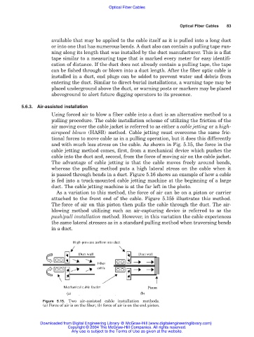
and with much less stress on the cable. As shown in Fig. 5.15, the force in the
cable jetting method comes, first, from a mechanical device which pushes the
cable into the duct and, second, from the force of moving air on the cable jacket.
The advantage of cable jetting is that the cable moves freely around bends,
whereas the pulling method puts a high lateral stress on the cable when it
is passed through bends in a duct. Figure 5.16 shows an example of how a cable
is fed into a truck-mounted cable jetting machine at the beginning of a large
duct. The cable jetting machine is at the far left in the photo.
As a variation to this method, the force of air can be on a piston or carrier
attached to the front end of the cable. Figure 5.15b illustrates this method.
The force of air on this piston then pulls the cable through the duct. The air-
blowing method utilizing such an air-capturing device is referred to as the
push/pull installation method. However, in this variation the cable experiences
the same lateral stresses as in a standard pulling method when traversing bends
in a duct.
Figure 5.15. Two air-assisted cable installation methods.
(a) Force of air is on the fiber; (b) force of air is on the end piston.
Downloaded from Digital Engineering Library @ McGraw-Hill (www.digitalengineeringlibrary.com)
Copyright © 2004 The McGraw-Hill Companies. All rights reserved.
Any use is subject to the Terms of Use as given at the website.