
Page 118 - Optical Switching And Networking Handbook
P. 118
05_200023_CH04/Batesx 1/17/01 8:18 AM Page 103
Synchronous Digital Hierarchy 103
SDH Model OSI Model
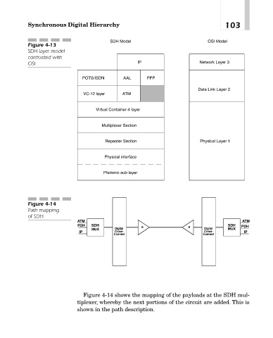
Figure 4-13
SDH layer model
contrasted with
OSI IP Network Layer 3
POTS/ISDN AAL PPP
Data Link Layer 2
VC-12 layer ATM
Virtual Container-4 layer
Multiplexer Section
Repeater Section Physical Layer 1
Physical interface
Photonic sub-layer
Figure 4-14
Path mapping
of SDH
ATM ATM
PDH SDH SDH PDH
MUX Digital R R Digital MUX
IP Cross- Cross- IP
Connect Connect
Figure 4-14 shows the mapping of the payloads at the SDH mul-
tiplexer, whereby the next portions of the circuit are added. This is
shown in the path description.