
Page 57 - Optical Switching And Networking Handbook
P. 57
03_200023_CH02/Batesx 1/17/01 8:17 AM Page 42
42 Chapter 2
by the geometry of the track. The same holds true with multimode
fibers. By adding some length to the path in the center and shorten-
ing the path on the outer edges, the playing field is leveled.This con-
cept makes it much easier to manufacture the glass by pulling the
thicknesses differently.
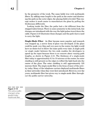
Looking inside the fiber, the paths look a bit different from the
stepped index format.There is some symmetry to the initial look, but
changes are introduced with the way the light pulses travel down the
cable. Figure 2-10 illustrates these changes and the path that is used
to carry the light.
Single-Mode Fiber As fiber became more popular and research
was stepped up, a newer form of glass was developed. If the glass
could be made very thin and very pure in the center, the light would
have no choice but to follow the same path every time. A single path
(or single mode) between the two ends enables the developers to
speed up the input because there is no concern about varying path
lengths, as shown in Figure 2-11. The thickness of a single-mode
fiber today is approximately 8.3 to 10 microns at the center.An outer
cladding is still present on the edges to reflect the light back into the
center of the glass. The outer cladding is still approximately 125
microns thick. The single-mode fiber is the focus of most of the activ-
ity today. Many of the telephone carriers deployed multimode fibers
in their networks when they were first introduced. However, over the
years, multimode fiber has given way to single-mode fiber through-
out the public carrier networks.
Figure 2-10
The various paths
changed using
graded index
multimode fiber