
Page 75 - Optical Switching And Networking Handbook
P. 75
04_200023_CH03/Batesx 1/17/01 9:42 AM Page 60
60 Chapter 3
SONET: A Means of Synchronizing
Digital Signals
SONET involves synchronization of the digital signals arriving at
the equipment. Keep in mind that the signals may be introduced in
one of three ways. Therefore, it is important to attempt to get every-
thing on a common set of clocking mechanisms. In digital transmis-
sion, the normal way of synchronizing traffic is to draw a common
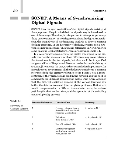
clocking reference. In the hierarchy of clocking, systems use a stra-
tum clocking architecture. The stratum references in North America
come in a four-level architecture. These are shown in Table 3-1.
In a set of synchronous signals, the digital transitions in the sig-
nals occur at the same rate. A phase difference may occur between
the transitions in the two signals, but this would be in specified
ranges and limits.The phase differences can be the result of delay in
systems, jitter across the link, or other transmission impairments. In
a synchronous environment, all the clocks are traceable to a common
reference clock (the primary reference clock). Figure 3-5 is a repre-
sentation of the various clocks used in the network and the need to
compensate for different transmission paths. This figure assumes
that the different switching systems at the various locations can
buffer the data to overcome jitter or phase problems. Buffers are
used to compensate for the different transmission media, the various
path lengths that can be taken, and the operation of the switching
and multiplexing systems.
Table 3-1
Stratum Reference Location Used Accuracy
Summary of
Clocking Systems 1 Primary reference drawn 1 pulse in 10 –11
from GPS or the national
reference atomic clock
2 Toll offices 1.6 pulses in 10 –8
(long distance COs)
3 End offices (local COs) 4.6 pulses in 10 –6
4 Customer equipment 32 pulses in 10 –6
(multiplexer, channel
bank, and so on)