
Page 165 - Optofluidics Fundamentals, Devices, and Applications
P. 165
140 Cha pte r Se v e n
Microfluidic
channel
Beam path
Collimated beam
Fiber Bragg Graded index Graded index Fiber Bragg
grating fiber fiber grating
SU-8
Alignment
channel
Microfluidic
channel
50 μm 100 μm
Glass substrate
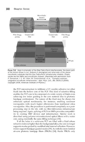
FIGURE 7-2 (top) A schematic of the fi ber Fabry-Perot interferometer, the beam path
of the device shown in red. (bottom) A photograph and schematic of the planar
microfl uidic substrate that the fi ber Fabry-Perot refractometer inhabits. Clearly
visible are the SMFs and microfl uidic channel. (Reprinted with permission from
P. Domachuk, I. C. M. Littler, M. Cronin-Golomb, et al., “Compact resonant
integrated microfl uidic refractometer,” Appl. Phys. Lett., 88, 093513 (2006).
Copyright 2006, American Institute of Physics.)
the PCF microstructure to infiltrate a UV curable adhesive (or other
fluid) into the hollow core of the PCF. This kind of selective filling
enables the PCF core to be composed of a wide variety of fluids even
achieving low index guiding in the core material due to photonic
bandgap confinement. The nature of the fluid may be chosen for
enhanced optical nonlinearity, for instance, enabling nonlinear
waveguides with much higher efficiencies than traditional silica
waveguides. Also, the procedure is performed completely as a post-
processing step in the lab, with no fiber-fabrication infrastructure
being required. Again, splicing of PCFs to SMFs provides compatibil-
ity to existing SMF devices and infrastructure. Similar work is
described using polymer microstructured optical fibers with a water
core, using essentially the same filling technique [58].
If all the holes in a solid-core PCF are filled with a fluid whose
refractive index is higher than the background silica, the core no longer
supports modes guided by modified total internal reflection. However,
it does support bandgap-guided modes [59]. As with the more familiar
air-core photonic bandgap fibers (PBGFs) [18], fluidic PBGFs only