
Page 166 - Optofluidics Fundamentals, Devices, and Applications
P. 166
Optofluidic Photonic Crystal Fibers: Pr operties and Applications 141
1
II
UV
Cleaving
2
Filling
UV
Cleaving
3
Filling
UV
Filling Cleaving 4
(a)
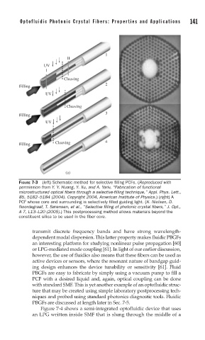
FIGURE 7-3 (left) Schematic method for selective fi lling PCFs. (Reproduced with
permission from Y. Y. Huang, Y. Xu, and A. Yariv, “Fabrication of functional
microstructured optical fi bers through a selective-fi lling technique,” Appl. Phys. Lett.,
85, 5182–5184 (2004). Copyright 2004, American Institute of Physics.) (right) A
PCF whose core and surrounding is selectively fi lled guiding light. (K. Nielsen, D.
Noordegraaf, T. Sørensen, et al., “Selective fi lling of photonic crystal fi bers,” J. Opt.,
A 7, L13–L20 (2005).) This postprocessing method allows materials beyond the
constituent silica to be used in the fi ber core.
transmit discrete frequency bands and have strong wavelength-
dependent modal dispersion. This latter property makes fluidic PBGFs
an interesting platform for studying nonlinear pulse propagation [60]
or LPG-mediated mode coupling [61]. In light of our earlier discussion,
however, the use of fluidics also means that these fibers can be used as
active devices or sensors, where the resonant nature of bandgap guid-
ing design enhances the device tunability or sensitivity [61]. Fluid
PBGFs are easy to fabricate by simply using a vacuum pump to fill a
PCF with a desired liquid and, again, optical coupling can be done
with standard SMF. This is yet another example of an optofluidic struc-
ture that may be created using simple laboratory postprocessing tech-
niques and probed using standard photonics diagnostic tools. Fluidic
PBGFs are discussed at length later in Sec. 7-5.
Figure 7-4 shows a semi-integrated optofluidic device that uses
an LPG written inside SMF that is slung through the middle of a