
Page 169 - Optofluidics Fundamentals, Devices, and Applications
P. 169
144 Cha pte r Se v e n
To
vacuum
line
β core
Fuild
(a)
0
25°C
35°C 40°C Air-
Transmission (dB) –3 60°C holes
–6
80°C
100°C Material
120°C
1400 1450 1500 1550 1600
Wavelength (nm)
(b)
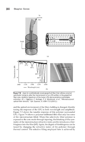
FIGURE 7-5 (top) An optofl uidically tuned grapefruit fi ber that utilizes external
optofl uidic tuning to alter the transmission of an LPG written in the grapefruit
fi ber core. (bottom) Spectrum of the tuned LPG demonstrating controllable
extinction. (B. J. Eggleton, C. Kerbage, P. S. Westbrook, et al., “Microstructured
optical fi ber devices,” Opt. Express, 9, 698–713 (2001).)
and the optical environment of the fiber cladding is changed, thereby
tuning the response of the LPG in both wavelength and amplitude.
Figure 7-5 shows the tunable response of this polymer surrounded
LPG. Figure 7-6 shows a polymer-infiltrated fiber that only has some
of the microstructure filled. When this selectively filled polymer is
exposed to the core mode through tapering, the breaking of the sym-
metry of the microstructure refractive index profile introduces a bire-
fringence into the fiber [65]. Again, the degree of birefringence can be
tuned by changing the refractive index of the polymer through
thermal control. The selective filling employed here is achieved by