
Page 172 - Optofluidics Fundamentals, Devices, and Applications
P. 172
Optofluidic Photonic Crystal Fibers: Pr operties and Applications 147
Integrated Long-period
(b)
heaters grating
Splice V pump V grat Splice
(c)
V pump V grat High-index fluid
Core Cladding Low-index fluid
mode mode
0 0
Transmission (dB) –4 T grat 1558 20 T grat (°C) 80 110 Transmission (dB) –4 T pump Γ LPG 0.8 150 Temp (°C)
1.0
50
–8
–8
100
0.6
71°C
54°C
0.2
98°C
1550
–12 25°C λres (nm) 1554 –12 25°C 0.4 50
0
83°C
L grat (cm)
116°C 1546 126°C 0 12 3 4
1530 1540 1550 1560 1570 1580 1530 1540 1550 1560 1570
(a) (b)
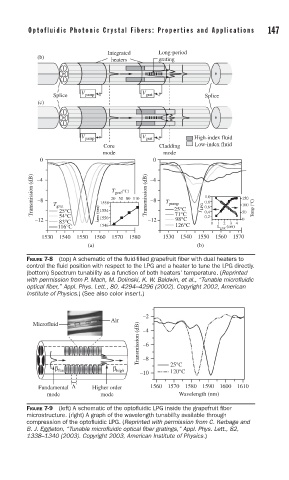
FIGURE 7-8 (top) A schematic of the fl uid-fi lled grapefruit fi ber with dual heaters to
control the fl uid position with respect to the LPG and a heater to tune the LPG directly.
(bottom) Spectrum tunability as a function of both heaters’ temperature. (Reprinted
with permission from P. Mach, M. Dolinski, K. W. Baldwin, et al., “Tunable microfl uidic
optical fi ber,” Appl. Phys. Lett., 80, 4294–4296 (2002). Copyright 2002, American
Institute of Physics.) (See also color insert.)
–2
Air
Transmission (dB) –6
Microfluid –4
β –8 25°C
β fun high 120°C
–10
Fundamental Λ Higher order 1560 1570 1580 1590 1600 1610
mode mode Wavelength (nm)
FIGURE 7-9 (left) A schematic of the optofl uidic LPG inside the grapefruit fi ber
microstructure. (right) A graph of the wavelength tunability available through
compression of the optofl uidic LPG. (Reprinted with permission from C. Kerbage and
B. J. Eggleton, “Tunable microfl uidic optical fi ber gratings,” Appl. Phys. Lett., 82,
1338–1340 (2003). Copyright 2003, American Institute of Physics.)