
Page 173 - Optofluidics Fundamentals, Devices, and Applications
P. 173
148 Cha pte r Se v e n
Grapefruit fibers provide a wealth of potential optofluidic
designs to be realized, thanks both to the easily accessible fiber
microstructure and to the SMF compatibility. Combined with fiber
post-processing techniques such as tapering and holographic grat-
ing writing, optofluidic tuning has not only allowed a broad range
of optical components to be fabricated but also endowed those com-
ponents with significantly more flexibility that is available through
traditional fiber fabrication methods.
7-3 Optofluidic Transverse Fiber Quasi-2-D
Photonic Crystals
PCFs are designed for use as waveguides. They guide light along their
length through confinement provided by photonic bandgap [68] or
effective refractive index [17] effects. However, if light is introduced
into the side of the PCF, that is “probed transversely,” the microstruc-
ture acts essentially as a planar photonic crystal [7], displaying a
characteristic range of reflected wavelengths (the “band gap”) [69].
Further, the hollow inclusions that define the PCF microstructure are a
natural home for microfluids that can change the wavelength of
the transverse bandgap or be moved to dynamically modulate the
response of the transverse fiber [70]. In light of these considerations,
transverse PCFs provide an excellent platform for optofluidic tuning.
7-3-1 Optofluidic Transverse PCF
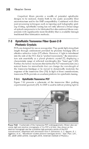
Figure 7-10 presents a schematic of the transverse fiber probing
experimental geometry [7]. An SMF is used to deliver probing light to
CCD
Launch fibre
camera
Polarizer 10x Objective K
Lens
Source OSA
Γ M
Transverse
fibre Detector
fibre
Fibre chuck
FIGURE 7-10 A schematic of the transverse PCF probing geometry. Shown also are
visible light and electron micrographs of the PCF end face. Also shown on the
electron micrograph are the crystalline high-symmetry points of the PCF
microstructure. (Reprinted with permission from P. Domachuk, H. C. Nguyen, B. J.
Eggleton, et al., “Microfl uidic tunable photonic band-gap device,” Appl. Phys. Lett.,
84, 1838–1840 (2004). Copyright 2004, American Institute of Physics.)