
Page 176 - Optofluidics Fundamentals, Devices, and Applications
P. 176
Optofluidic Photonic Crystal Fibers: Pr operties and Applications 151
TE polarization TM polarization
0 0
–10 –10
–20 –20
n = 1.45 n = 1.45
–30 –30
–10 –10
–20 –20
n = 1.50 n = 1.50
–30 –30
–10 n = 1.55 –10 n = 1.55
Insertion loss (dB) –20 n = 1.60 Insertion loss (dB) –20 n = 1.60
–30
–30
–10
–10
–20
–20
–30
–10
–10 –30
–20 –20
n = 1.65 n = 1.65
–30 –30
–10 –10
–20 –20
n = 1.70 n = 1.70
–30 –30
–10 –10
–20 –20
n = 1.75 n = 1.75
–30 –30
1.0 1.2 1.4 1.6 1.0 1.2 1.4 1.6
Wavelength (μm) Wavelength (μm)
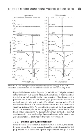
FIGURE 7-13 The emergence of the second order partial bandgap in the Γ-M
orientation as the refractive indices of the inclusions are increased using fl uids.
Figure 7-13 shows a series of spectra (in both TE and TM polarizations)
of the transverse PCF in the Γ-M orientation as fluids of different refrac-
tive index are infiltrated into the microstructure. Also shown are the
positions and widths of the partial gaps predicted by plane wave
method for a given inclusion index. For a fluid refractive index of 1.45,
the fluid renders the PCF practically transparent and the transmission
spectrum is featureless. As the refractive index of the fluid and the
inclusions increases, the partial bandgap begins to appear in the spec-
tra of both polarizations. As the refractive index contrast of the PCF
continues to increase, the bandgap becomes broader and moves to lon-
ger wavelengths, as predicted by the plane wave method.
7-3-2 Dynamic Optofluidic Attenuator
Since the fluid inside the PCF microstructure is mobile, this mobil-
ity may be used to create a reconfigurable photonic crystal switch
[70]. Figure 7-14 shows the optical experimental setup: it is the