
Page 180 - Optofluidics Fundamentals, Devices, and Applications
P. 180
Optofluidic Photonic Crystal Fibers: Pr operties and Applications 155
intensity of the two beams in the device is not necessarily equal. Since
a fluid-air interface is used to provide optofluidic tuning of the device,
the mobility of the fluid allows the visibility of the interferometer
modulation to be tuned simply by moving the meniscus with respect
to the center of the beam. To change the wavelength of the Mach-
Zehnder resonances, the diameter of the square capillary or the
refractive index of the fluid is changed.
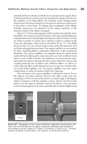
Figure 7-17 shows photographs of the tunable microfluidic inter-
ferometer. The meniscus used to introduce the optical path difference
is formed between a short length of deionized water of index 1.33 and
air inside a section of square silica capillary. Light is coupled in the
transverse direction in the manner described in Sec. 7-3. The SMFs
shown in Fig. 7-17 are used to transversely probe the meniscus with
an 80-μm spacing between them. The square capillary is surrounded
by index matching fluid to minimize reflections at the component
interfaces. The square capillary was tapered using the flame brush
method [31]. Its dimensions were reduced to an inner width of 10 μm
and an outer width of 80 μm. The tapering was performed to mini-
mize beam divergence through the device and, therefore, enhance the
coupling between the excitation and collection fibers as well as to
ensure that the fiber mode did not interact excessively with the inte-
rior walls of the capillary core. The square capillary was seen, upon
examination, to retain its square profile after tapering.
The meniscus in the square capillary is inherently curved, due to
the balance of surface tensions between the silica, water and sur-
rounding air. This curved surface forms a contact angle of 40 degrees
where it intersects with the capillary surface. Figure 7-18 shows this
behavior in the square capillaries used in the device. This curvature
of the meniscus presents an issue optically due to incident light being
10 μm
S S
M M
F F
80 μm
FIGURE 7-17 Photographs of the compact optofl uidic single-beam interferometer with
views from the front (left) and top (right), showing the refractive-index-matching oil
surrounding the square capillary. (C. Grillet, P. Domachuk, V. Ta’eed, et al., “Compact
tunable microfl uidic interferometer,” Opt. Express, 12, 5440–5447 (2004).)