
Page 185 - Optofluidics Fundamentals, Devices, and Applications
P. 185
160 Cha pte r Se v e n
0
–10 7 7th 6 6th 5 5th 4 4th
–20 0 n D = 1.64
Transmission (dB) –10 7 7th 6 6th 5 5th n = 1.62
4 4th
–20
–30
D
–10 0
4th
–20 6th 5th 3rd
–30 n = 1.58
D
–40
700 800 900 1000 1100 1200 1300 1400
Wavelength (nm)
(a)
0
–10
Transmission (dB) –20 ΔT = 0°C
–30
ΔT = 30°C (Δn = 0.014)
ΔT = 78°C (Δn = 0.036)
ΔT = 96°C (Δn = 0.045)
–40 ΔT = 115°C (Δn = 0.053)
750 800 850 900 950 1000
Wavelength (nm)
(b)
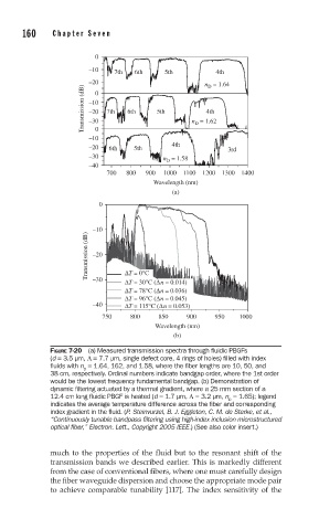
FIGURE 7-20 (a) Measured transmission spectra through fl uidic PBGFs
(d = 3.5 μm, Λ = 7.7 μm, single defect core, 4 rings of holes) fi lled with index
fl uids with n = 1.64, 162, and 1.58, where the fi ber lengths are 10, 50, and
D
38 cm, respectively. Ordinal numbers indicate bandgap order, where the 1st order
would be the lowest frequency fundamental bandgap. (b) Demonstration of
dynamic fi ltering actuated by a thermal gradient, where a 25 mm section of a
12.4 cm long fl uidic PBGF is heated (d = 1.7 μm, Λ = 3.2 μm, n = 1.65); legend
D
indicates the average temperature difference across the fi ber and corresponding
index gradient in the fl uid. (P. Steinvurzel, B. J. Eggleton, C. M. de Sterke, et al.,
“Continuously tunable bandpass fi ltering using high-index inclusion microstructured
optical fi ber,” Electron. Lett., Copyright 2005 IEEE.) (See also color insert.)
much to the properties of the fluid but to the resonant shift of the
transmission bands we described earlier. This is markedly different
from the case of conventional fibers, where one must carefully design
the fiber waveguide dispersion and choose the appropriate mode pair
to achieve comparable tunability [117]. The index sensitivity of the