
Page 177 - Optofluidics Fundamentals, Devices, and Applications
P. 177
152 Cha pte r Se v e n
Tunable
source
SMF
Fluid
Heater
PCF
SMF
Detector
V
t
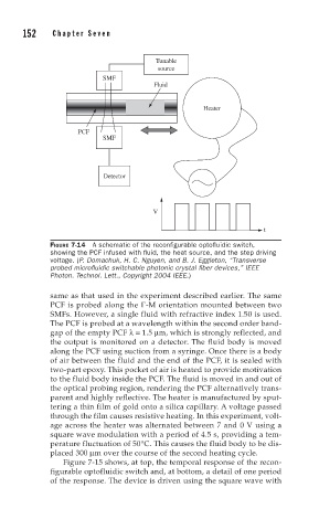
FIGURE 7-14 A schematic of the reconfi gurable optofl uidic switch,
showing the PCF infused with fl uid, the heat source, and the step driving
voltage. (P. Domachuk, H. C. Nguyen, and B. J. Eggleton, “Transverse
probed microfl uidic switchable photonic crystal fi ber devices,” IEEE
Photon. Technol. Lett., Copyright 2004 IEEE.)
same as that used in the experiment described earlier. The same
PCF is probed along the Γ-M orientation mounted between two
SMFs. However, a single fluid with refractive index 1.50 is used.
The PCF is probed at a wavelength within the second order band-
gap of the empty PCF λ= 1.5 μm, which is strongly reflected, and
the output is monitored on a detector. The fluid body is moved
along the PCF using suction from a syringe. Once there is a body
of air between the fluid and the end of the PCF, it is sealed with
two-part epoxy. This pocket of air is heated to provide motivation
to the fluid body inside the PCF. The fluid is moved in and out of
the optical probing region, rendering the PCF alternatively trans-
parent and highly reflective. The heater is manufactured by sput-
tering a thin film of gold onto a silica capillary. A voltage passed
through the film causes resistive heating. In this experiment, volt-
age across the heater was alternated between 7 and 0 V using a
square wave modulation with a period of 4.5 s, providing a tem-
perature fluctuation of 50°C. This causes the fluid body to be dis-
placed 300 μm over the course of the second heating cycle.
Figure 7-15 shows, at top, the temporal response of the recon-
figurable optofluidic switch and, at bottom, a detail of one period
of the response. The device is driven using the square wave with