
Page 174 - Optofluidics Fundamentals, Devices, and Applications
P. 174
Optofluidic Photonic Crystal Fibers: Pr operties and Applications 149
the transverse fiber. Once the light has interacted with the transverse
PCF, it is collected by another SMF and analyzed. These two SMFs are
carefully aligned using 3-D positioning stages to ensure the most effi-
cient possible coupling of light in the apparatus. The light source
used is a broadband thermal halogen bulb. When probing PCFs the
wavelength range of the source is chosen such that it intersects with
the partial photonic bandgap of the transverse PCF. A polarizer is
also inserted in-line and the SMF kept taut to control and maintain
polarization. The collected output light is spectrally analyzed on an
optical spectrum analyzer (OSA). Figure 7-10 also shows a close-up
photograph of the apparatus being used to probe a transverse PCF.
Shown are the two aligned SMFs used for probing and collection on
either side of a PCF, whose hexagonal microstructure is plainly visi-
ble. The PCF has circular air inclusions of diameter 800 nm with a
periodicity of 1.4 μm arranged in a hexagonal packing. The PCF sits
between two SMFs. One SMF delivers light from the thermal halogen
bulb with range 800 to 1700 nm. The polarizations are labeled TM for
electric field parallel to the length of the transverse fiber and TE for
the perpendicular orientation. The PCF is held in a rotational chuck
to allow orienting various crystal axes to the optical axis between the
SMFs and is visually aligned using a microscope to sit as central to
the SMF optical axes as possible. Also shown in Fig. 7-10 are the high-
symmetry points of the reciprocal lattice of the microstructure
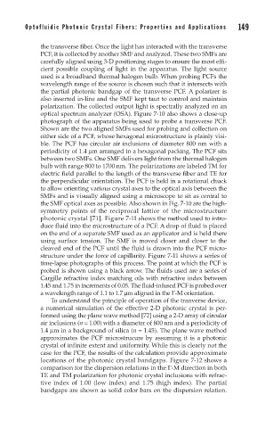
photonic crystal [71]. Figure 7-11 shows the method used to intro-
duce fluid into the microstructure of a PCF. A drop of fluid is placed
on the end of a separate SMF used as an applicator and is held there
using surface tension. The SMF is moved closer and closer to the
cleaved end of the PCF until the fluid is drawn into the PCF micro-
structure under the force of capillarity. Figure 7-11 shows a series of
time-lapse photographs of this process. The point at which the PCF is
probed is shown using a black arrow. The fluids used are a series of
Cargille refractive index matching oils with refractive index between
1.45 and 1.75 in increments of 0.05. The fluid-infused PCF is probed over
a wavelength range of 1.1 to 1.7 μm aligned in the Γ-M orientation.
To understand the principle of operation of the tranverse device,
a numerical simulation of the effective 2-D photonic crystal is per-
formed using the plane wave method [72] using a 2-D array of circular
air inclusions (n = 1.00) with a diameter of 800 nm and a periodicity of
1.4 μm in a background of silica (n = 1.45). The plane wave method
approximates the PCF microstrucure by assuming it is a photonic
crystal of infinite extent and uniformity. While this is clearly not the
case for the PCF, the results of the calculation provide approximate
locations of the photonic crystal bandgaps. Figure 7-12 shows a
comparison for the dispersion relations in the Γ-M direction in both
TE and TM polarization for photonic crystal inclusions with refrac-
tive index of 1.00 (low index) and 1.75 (high index). The partial
bandgaps are shown as solid color bars on the dispersion relation.