
Page 178 - Optofluidics Fundamentals, Devices, and Applications
P. 178
Optofluidic Photonic Crystal Fibers: Pr operties and Applications 153
1.2
1
Transmission (a.u.) 0.6
0.8
0.4
0.2
0 1 “On” state =
0.8 –7 dB
Transmission (a.u.) 0.4 1.5 s
–0.2
0 2.5 5 7.5 10 0.6
Time (s) Response time =
0.2
Rise time = 0.33 s
0
“Off” state = –30 dB
–0.2
0 1 2 3 4 5 6
Time (s)
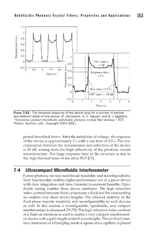
FIGURE 7-15 The temporal response of the device (top) for a number of periods
and (bottom) detail of one period. (P. Domachuk, H. C. Nguyen, and B. J. Eggleton,
“Transverse probed microfl uidic switchable photonic crystal fi ber devices,” IEEE
Photon. Technol. Lett., Copyright 2004 IEEE.)
period described above. After the initial rise of voltage, the response
of the device is approximately 2 s with a rise time of 0.5 s. The dis-
crimination between the transmission and reflection of the device
is 20 dB, arising from the high reflectivity of the photonic crystal
microstructure. The large response time of the structure is due to
the high thermal mass of the silica PCF [73].
7-4 Ultracompact Microfluidic Interferometer
Future photonic devices need broad tunability and reconfigurability.
Such functionality enables higher performance out of a given device
with clear integration and time/material investment benefits. Opto-
fluidic tuning enables these device attributes. The high refractive
index contrast between fluids or between a fluid and the surrounding
air enables very short device lengths. The inherent mobility of the
fluid phase imparts tunability and reconfigurability to such devices
as well. In this section, a reconfigurable, optofluidic, and compact
interferometer is discussed [74,75]. The high refractive index contrast
of a fluid-air meniscus is used to enable a very compact interferomet-
ric device with a path length under 8 wavelengths. The air-fluid inter-
face (meniscus) of a fluid plug inside a square silica capillary is placed