
Page 206 - Optofluidics Fundamentals, Devices, and Applications
P. 206
Adaptive Optofluidic Devices 181
Blazed
grating
Outlet
1 cm
Inlet
(e) (f)
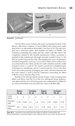
FIGURE 8-1 (Continued)
The first flow layer contains the main functional element of the
device—flat mirror channel. It can be filled with either pure water
from inlet 1 or salt solution from inlet 2 (see Fig. 8-1d). The salt solu-
tion has a refractive index that matches the index of PDMS. The
channels connecting the inlets and the outlet with the mirror are
completely sealed by the flexible membranes when a pressure is
applied to the membranes through channels (control lines) in the
second control layer of the chip. The membranes serve as pressure-
actuated integrated “push-up” valves [39]. Three of the control lines
are connected to the valves on the two inlet channels and the outlet
channel (valves 1, 2, and 5). The fourth control line (simultaneously
switching two membrane valves 3 and 4) and the vent in the flow
layer serve the purpose of purging the dead volumes between the
two inlet valves (1 and 2) and the T-junction connecting the inlets
with the mirror channel (Fig. 8-1d).
Results of the measurements for the beams 1 and 2 coming from
below and above (see Fig. 8-1c) the two orthogonal linear polariza-
tion states and the two switching states are summarized in Table 8-1
as values of insertion loss and extinction ratio in decibel (dB).
Bypass Exchange Bypass Exchange
TE, dB TE, dB TM, dB TM, dB
Laser 1 2 1 2 1 2 1 2
beam
Insertion
0.78 0.84 1.1 1.1 0.71 0.67 0.83 0.78
loss
Extinction
22.7 24.4 18.2 17.7 17.8 22.5 21.7 16.7
ratio
TABLE 8-1 Insertion Loss and Extinction Ratio (in dB) for Transmitted and
Reflected Beams in the Two States of the Switch and for Two Inputs at TE and TM