
Page 305 - Optofluidics Fundamentals, Devices, and Applications
P. 305
Optofluidic Resonators 279
The minimum intensity is given by
⎡ A ⎤ 2 ⎡ A ⎤ 2
⎢ ⎣ 1 − AT⎦ ⎥ ⎢ ⎣ 1 − AT⎦ ⎥ T 2
+
+
I = I = I = I (12-33)
min 0 1 + K 0 ⎡ ( + R) ⎤ 0 (1+ R ) 2
2
)
1
⎢ 2 ⎥
⎣ (1− R ) ⎦
The achievable contrast between maximum and minimum intensity
inside the Fabry-Perot resonator is given by
I max = ( +1 R) 2 (12-34)
I ( −1 R) 2
min
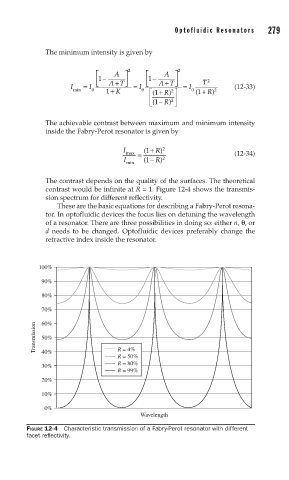
The contrast depends on the quality of the surfaces. The theoretical
contrast would be infinite at R = 1. Figure 12-4 shows the transmis-
sion spectrum for different reflectivity.
These are the basic equations for describing a Fabry-Perot resona-
tor. In optofluidic devices the focus lies on detuning the wavelength
of a resonator. There are three possibilities in doing so: either n, θ, or
d needs to be changed. Optofluidic devices preferably change the
refractive index inside the resonator.
100%
90%
80%
70%
60%
Transmission 50%
R = 4%
40%
R = 50%
R = 80%
30%
R = 99%
20%
10%
0%
Wavelength
FIGURE 12-4 Characteristic transmission of a Fabry-Perot resonator with different
facet refl ectivity.