
Page 301 - Optofluidics Fundamentals, Devices, and Applications
P. 301
Optofluidic Resonators 275
and
α 2 ( 1 −|| 2
t )
P =|| 2 = (12-15)
E
i2 i2 ( 1+ α t ||) 2
A special case happens when α = | t | in Eqs. (12-14), when the internal
losses are equal to the coupling losses. The transmitted power
becomes zero. This is known in literature as critical coupling, which
is due to destructive interference.
In using the Eqs. (12-4) and (12-15), it is possible to get a good
idea of the behavior of a simplified basic ring resonator filter configu-
ration consisting of only one waveguide and one ring.
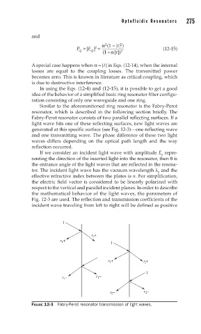
Similar to the aforementioned ring resonator is the Fabry-Perot
resonator, which is described in the following section briefly. The
Fabry-Perot resonator consists of two parallel reflecting surfaces. If a
light wave hits one of these reflecting surfaces, new light waves are
generated at this specific surface (see Fig. 12-3)—one reflecting wave
and one transmitting wave. The phase difference of these two light
waves differs depending on the optical path length and the way
reflection occurred.
If we consider an incident light wave with amplitude E repre-
0
senting the direction of the inserted light into the resonator, then θ is
the entrance angle of the light waves that are reflected in the resona-
tor. The incident light wave has the vacuum wavelength λ and the
0
effective refractive index between the plates is n. For simplification,
the electric field vector is considered to be linearly polarized with
respect to the vertical and parallel incident planes. In order to describe
the mathematical behavior of the light waves, the parameters of
Fig. 12-3 are used. The reflection and transmission coefficients of the
incident wave traveling from left to right will be defined as positive
1
t +
1
r + 1
1
r + t +
2
2
1
t – r –
1
1
– r –
t 2 2
FIGURE 12-3 Fabry-Perot resonator transmission of light waves.