
Page 298 - Optofluidics Fundamentals, Devices, and Applications
P. 298
272 Cha pte r T w e l v e
a
k
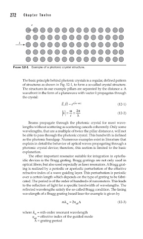
FIGURE 12-1 Example of a photonic crystal structure.
The basic principle behind photonic crystals is a regular, defined pattern
of structures as shown in Fig. 12-1, to form a so-called crystal structure.
The structures in our example pillars are separated by the distance a. A
wavefront in the form of a planewave with vector k propagates through
the crystal:
(
EH ~ e ikx−ω t) (12-1)
,
ω 2 π
k = = (12-2)
c λ
Beams propagate through the photonic crystal for most wave-
lengths without scattering as scattering cancels coherently. Only some
wavelengths, that are a multiple of twice the pillar distance a, will not
be able to pass through the photonic crystal. This bandwith is defined
as the photonic bandgap. Numerous examples exist in literature that
explain in detail the behavior of optical waves propagating through a
photonic crystal device; therefore, this section is limited to the basic
explanation.
The other important resonator suitable for integration in optoflu-
idic devices is the Bragg grating. Bragg gratings are not only used in
optical fibers, but also used especially as laser resonators. A Bragg grat-
ing is realized by a periodic or aperiodic perturbation of the effective
refractive index of a wave guiding layer. This perturbation is periodic
over a certain length which depends on the type of grating to be fabri-
cated. The period is of the order of hundreds of nanometers. This leads
to the reflection of light for a specific bandwidth of wavelengths. The
reflected wavelengths satisfy the so-called Bragg condition. The lasing
wavelength of a Bragg grating based laser for example is given by
mλ= 2 n Λ (12-3)
m eff
where λ = mth-order resonant wavelength
m
n = effective index of the guided mode
eff
Λ = grating period