
Page 88 - Optofluidics Fundamentals, Devices, and Applications
P. 88
Optofluidic Optical Components 69
0
(a)
S1
Transmission (dB) –20 ξ = 0.55
Crossroad 2 1 –10
Test channel
Microring –30 ξ = 0.6
ξ = 0.7
1 mm S2 –40
1551 1552 1553
λ (nm)
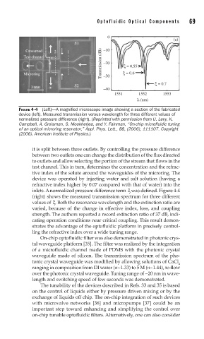
FIGURE 4-4 (Left)—A magnifi ed microscope image showing a section of the fabricated
device (left). Measured transmission versus wavelength for three different values of
normalized pressure difference (right). (Reprinted with permission from U. Levy, K.
Campbell, A. Groisman, S. Mookherjea, and Y. Fainman, “On-chip microfluidic tuning
of an optical microring resonator,” Appl. Phys. Lett., 88, (2006), 111107. Copyright
(2006), American Institute of Physics.)
it is split between three outlets. By controlling the pressure difference
between two outlets one can change the distribution of the flux directed
to outlets and allow selecting the portion of the stream that flows in the
test channel. This in turn, determines the concentration and the refrac-
tive index of the solute around the waveguides of the microring. The
device was operated by injecting water and salt solution (having a
refractive index higher by 0.07 compared with that of water) into the
inlets. A normalized pressure difference term ξ was defined. Figure 4-4
(right) shows the measured transmission spectrum for three different
values of ξ. Both the resonance wavelength and the extinction ratio are
varied, because of the change in effective index, loss, and coupling
strength. The authors reported a record extinction ratio of 37 dB, indi-
cating operation conditions near critical coupling. This result demon-
strates the advantage of the optofluidic platform in precisely control-
ling the refractive index over a wide tuning range.
On-chip optofluidic filter was also demonstrated in photonic crys-
tal waveguide platform [35]. The filter was realized by the integration
of a microfluidic channel made of PDMS with the photonic crystal
waveguide made of silicon. The transmission spectrum of the pho-
tonic crystal waveguide was modified by allowing solutions of CaCl
2
ranging in composition from DI water (n~1.33) to 5 M (n~1.44), to flow
over the photonic crystal waveguide. Tuning range of ~20 nm in wave-
length and switching speed of few seconds was demonstrated.
The tunability of the devices described in Refs. 33 and 35 is based
on the control of liquids either by pressure driven mixing or by the
exchange of liquids off chip. The on-chip integration of such devices
with microvalve networks [36] and micropumps [37] could be an
important step toward enhancing and simplifying the control over
on-chip tunable optofluidic filters. Alternatively, one can also consider