
Page 282 - Organic Electronics in Sensors and Biotechnology
P. 282
An Intr oduction to Or ganic Photodetectors 259
Noise-free
R
resistor
Z
C
C σ VC (f ) = σ ∼ V Δf R + Z C
σ ∼ Voltage
V
noisesource
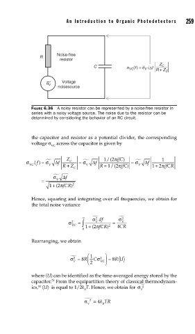
FIGURE 6.36 A noisy resistor can be represented by a noise-free resistor in
series with a noisy voltage source. The noise due to the resistor can be
determined by considering the behavior of an RC circuit.
the capacitor and resistor as a potential divider, the corresponding
voltage σ across the capacitor is given by
VC
σ () f = f Δ Z C = f Δ 1 /(2 πjfC ) = σ f Δ 1
σ
σ
VC V R + Z V R + 1 /(2 πjfC) ) V 12
+ πjfCR
C
f Δ
σ
= V
1 + 2 ) 2
( πfCR
Hence, squaring and integrating over all frequencies, we obtain for
the total noise variance
2
∞ σ df σ 2
=
σ VC ∫ V 2 = V
2
0 1 + ( 2 πfCR) 4CR
Rearranging, we obtain
2
σ = 8 R ⎛ ⎜ 1 C σ 2 ⎞ ⎟ = 8 R U
V ⎝ 2 VC ⎠
where 〈U〉 can be identified as the time-averaged energy stored by the
capacitor. From the equipartition theory of classical thermodynam-
51
ics, 〈U〉 is equal to 1/2k T. Hence, we obtain for σ 2
51
B V
σ 2 = 4 kTR
V B