
Page 280 - Organic Electronics in Sensors and Biotechnology
P. 280
An Intr oduction to Or ganic Photodetectors 257
0.5
2
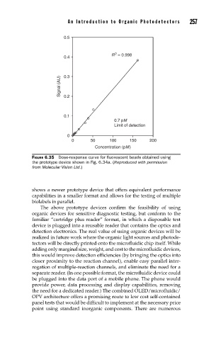
R = 0.998
0.4
Signal (AU) 0.3
0.2
0.1
0.7 pM
Limit of detection
0
0 50 100 150 200
Concentration (pM)
FIGURE 6.35 Dose-response curve for fl uorescent beads obtained using
the prototype device shown in Fig. 6.34a. (Reproduced with permission
from Molecular Vision Ltd.)
shows a newer prototype device that offers equivalent performance
capabilities in a smaller format and allows for the testing of multiple
biolabels in parallel.
The above prototype devices confirm the feasibility of using
organic devices for sensitive diagnostic testing, but conform to the
familiar “cartridge plus reader” format, in which a disposable test
device is plugged into a reusable reader that contains the optics and
detection electronics. The real value of using organic devices will be
realized in future work where the organic light sources and photode-
tectors will be directly printed onto the microfluidic chip itself. While
adding only marginal size, weight, and cost to the microfluidic devices,
this would improve detection efficiencies (by bringing the optics into
closer proximity to the reaction channel), enable easy parallel inter-
rogation of multiple-reaction channels, and eliminate the need for a
separate reader. (In one possible format, the microfluidic device could
be plugged into the data port of a mobile phone. The phone would
provide power, data processing and display capabilities, removing
the need for a dedicated reader.) The combined OLED/microfluidic/
OPV architecture offers a promising route to low cost self-contained
panel tests that would be difficult to implement at the necessary price
point using standard inorganic components. There are numerous