
Page 101 - PDA Robotics Using Your Personal Digital Assistant to Control Your Robot
P. 101
PDA 05 5/30/03 11:35 AM Page 77
Chapter 5 / The Electronics
the device has powered up, is successfully initialized, and is ready
for service. This signal is intended to be connected to the DSR input
of the host controller. If the host controller was directly connected to
an IrDA standard primary device using a serial cable (the MCP2150 is
not present), the host controller would be connected to the primary
device’s data transfer rate (DTR) output signal. The MCP2150 gener-
ates the CTS signal locally because of buffer limitations. Only the
transceiver’s TXD and RXD signals are carried back and forth to the
primary device. The MCP2150 emulates a three-wire serial connec-
tion (TXD, RXD, and GND).
The code for the PIC16F876 used in PDA Robot creates a three-wire
serial connection with the MCP2150 using the following line of code.
See Chapter 7: Programming the PIC16F876 Microcontroller.
#use rs232(baud=115200, xmit=PIN_B1, rcv=PIN_B0, stream=PDA)
Optical Transceiver
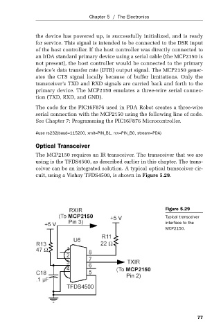
The MCP2150 requires an IR transceiver. The transceiver that we are
using is the TFDS4500, as described earlier in this chapter. The trans-
ceiver can be an integrated solution. A typical optical transceiver cir-
cuit, using a Vishay TFDS4500, is shown in Figure 5.29.
Figure 5.29
Typical transceiver
interface to the
MCP2150.
77