
Page 102 - PDA Robotics Using Your Personal Digital Assistant to Control Your Robot
P. 102
PDA 05 5/30/03 11:35 AM Page 78
PDA Robotics
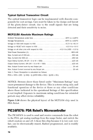
Typical Optical Transceiver Circuit
The optical transceiver logic can be implemented with discrete com-
ponents for cost savings. Care must be taken in the design and layout
of the photo-detect circuit, due to the small signals that are being
detected and their sensitivity to noise.
MCP2150 Absolute Maximum Ratings
Ambient Temperature under bias . . . . . . . . . . . . . . . . . . . . . . . . . . . . –40°C to +125°C
Storage Temperature. . . . . . . . . . . . . . . . . . . . . . . . . . . . . . . . . . . . . –65°C to +150°C
Voltage on VDD with respect to VSS . . . . . . . . . . . . . . . . . . . . . . . . . . –0.3 V to +6.5 V
Voltage on RESET with respect to VSS . . . . . . . . . . . . . . . . . . . . . . . . . –0.3 V to +14 V
Voltage on all other pins with respect to VSS . . . . . . . . . . . . . . . –0.3 V to (VDD + 0.3 V)
Total Power Dissipation (1). . . . . . . . . . . . . . . . . . . . . . . . . . . . . . . . . . . . . . . 800 mW
Max. Current out of VSS pin . . . . . . . . . . . . . . . . . . . . . . . . . . . . . . . . . . . . . . 300 mA
Max. Current into VDD pin . . . . . . . . . . . . . . . . . . . . . . . . . . . . . . . . . . . . . . . 250 mA
Input Clamp Current, IIK (VI < 0 or VI > VDD). . . . . . . . . . . . . . . . . . . . . . . . . . ±20 mA
Output Clamp Current, IOK (V0 < 0 or V0 > VDD). . . . . . . . . . . . . . . . . . . . . . . ±20 mA
Max. Output Current sunk by any Output pin . . . . . . . . . . . . . . . . . . . . . . . . . . . . 25 mA
Max. Output Current sourced by any Output pin. . . . . . . . . . . . . . . . . . . . . . . . . . 25 mA
Note 1: Power Dissipation is calculated as follows:
PDIS = VDD x {IDD - ∑ IOH} + ∑ {(VDD-VOH) x IOH} + ∑(VOL x IOL)
NOTICE: Stresses above those listed under “Maximum Ratings” may
cause permanent damage to the device. This is a stress rating only, and
functional operation of the device at those or any other conditions
above those indicated in the operational listings of this specification
is not implied. Exposure to maximum rating conditions for extended
periods may affect device reliability.
Figure 5.30 shows the physical layout of the MCP2150 chip used in
PDA Robot.
PIC16F876: PDA Robot’s Microcontroller
The PIC16F876 is used to send and receive commands from the robot
to the PDA, get analog readings from the range finder, and switch the
robot’s motors on and off. I chose this chip because it is low cost, very
fast, can be electronically erased, flashed programmed, and is readily
available.
78