
Page 215 - Automobile Mechanical and Electrical Systems Automotive Technology Vehicle Maintenance and Repair (Vehicle Maintenance Repr Nv2) by Tom Denton
P. 215
2
Engine systems 199
Figure 2.241 Fuel injection and ignition components from an earlier Motronic system. (Source:
Bosch Media)
Engine
speed
Engine load
(MAP)
Coolant
temperature Fuel pump
Air Fuel
temperature injectors
Fuel rail Idle control
temperature ECU actuator
Throttle
position Diagnostics
EGO
sensor
Battery
voltage
Other
system links
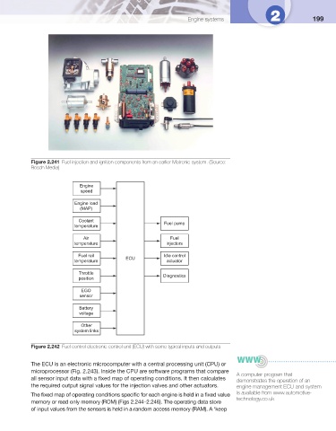
Figure 2.242 Fuel control electronic control unit (ECU) with some typical inputs and outputs
The ECU is an electronic microcomputer with a central processing unit (CPU) or
microprocessor ( Fig. 2.243 ). Inside the CPU are software programs that compare
A computer program that
all sensor input data with a fi xed map of operating conditions. It then calculates
demonstrates the operation of an
the required output signal values for the injection valves and other actuators. engine management ECU and system
is available from www.automotive-
The fi xed map of operating conditions specifi c for each engine is held in a fi xed value
technology.co.uk
memory or read only memory (ROM) ( Figs 2.244–2.246 ). The operating data store
of input values from the sensors is held in a random access memory (RAM). A ‘keep