
Page 218 - Automobile Mechanical and Electrical Systems Automotive Technology Vehicle Maintenance and Repair (Vehicle Maintenance Repr Nv2) by Tom Denton
P. 218
2
202 Automobile mechanical and electrical systems
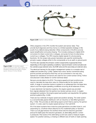
Figure 2.248 Injection wiring harness
Other programs in the CPU monitor the system and sensor data. They
provide fault diagnosis and limp-home or a limited operation strategy in the
event of any defects being detected. Other components in the ECU provide
signal amplifi cation and pulse shaping. This includes analogue to digital (A/D)
converters for direct current (d.c.) voltages, and pulse formers for alternating
current (a.c.) voltages. The CPU requires digital signals for all processing
functions. On the output side, power transistors are used for switching the
actuator supply voltages either to the components or to an earth or ground point.
The ECU also operates the emission control components at appropriate times
depending on the engine operating conditions. Typical emission control actuators are
Figure 2.249 An inductive speed the canister purge solenoid valve, the EGR valve and the secondary air solenoid valve.
sensor produces a sine-wave signal, the
frequency being proportional to engine The electrical harness for the engine management system is a complex set of
speed. (Source: Denso Media)
cables and sockets ( Fig. 2.248 ). Cables have colour and/or numerical coding
and the sockets are keyed so that they can be connected in one way only.
Special low-resistance connectors are used for low-current sensor wiring. Follow
manufacturer’s data sheets for further technical detail.
Sensors provide data to the ECU. The engine speed and load conditions are
used to calculate the base time value (in milliseconds) for the injector pulse
width. A range of correction factors is added to or subtracted from the base time
value to suit the engine operating conditions occurring at all instances of time.
In early electronic fuel injection systems, the engine speed was provided
from signals obtained from the ignition low-tension primary circuit. In engine
management systems, the engine speed and position are required for the ignition
and fuel systems ( Fig. 2.249 ).
There are two methods of engine speed and position sensing. The older system
is a conventionally geared distributor with an inductive or Hall effect generator
( Fig. 2.250 ). This provides an alternating signal current that is used by the ignition
system. It is also used for engine speed sensing in the fuel ECM.
All of the latest systems have inductive pulse generators mounted close to, and
responding to, a toothed wheel attached to the crankshaft pulley or fl ywheel.
There is an air gap between the toothed wheel and the inductive generator
and as the teeth pass the inductive generator, an alternating electric current
is produced. The waves of the alternating current are used to measure engine
speed. For position sensing, a missing or different size of tooth or mask opening