
Page 219 - Automobile Mechanical and Electrical Systems Automotive Technology Vehicle Maintenance and Repair (Vehicle Maintenance Repr Nv2) by Tom Denton
P. 219
2
Engine systems 203
Figure 2.250 Distributor for engine speed sensing on early systems
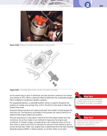
Figure 2.251 Camshaft position sensor. (Source: Ford Motor Company)
on the sensor ring is used. A distributor can also provide a reference for number Key fact
one cylinder at TDC. When a sensor is fi tted to determine the crankshaft position,
this is suitable for continuous injection systems. For sequential injection, a camshaft
position sensor is used to recognize
For sequential injection, a camshaft position sensor is used to recognize the the position of number one cylinder.
position of number one cylinder ( Fig. 2.251 ). The ECU is then able to follow the
engine fi ring order.
Inductive sensors produce an output pulse each time a lobe or tooth passes the
inductive coil. The frequency and pattern of the pulses are used by the ECU to
determine the engine speed and position.
The fuel requirement is calculated in the ECU from the engine speed and load Key fact
conditions. An air fl ow meter is one method of measuring the engine load Inductive sensors produce an output
conditions. A variable voltage, corresponding to the measured value at the air pulse each time a lobe or tooth
fl ow meter, is used by the ECU to calculate the amount of fuel needed to give a passes the inductive coil.
correct air/fuel ratio. Often now, engine load is determined from the inlet manifold
absolute pressure (MAP). In these systems, an air fl ow meter is not used.