
Page 238 - Petroleum and Gas Field Processing
P. 238
are used when water treatment is performed under pressures above the
atmospheric pressure. These equipment are normally large in volume to
provide residence time that is sufficiently long (10–30 min) for the
coalescence and gravity separation of the oil droplets.
Pressure vessels are more expensive than atmospheric tanks.
However, the choice is controlled by the overall requirements of the
water treatment system. Pressure vessels are normally preferred over
atmospheric tanks for the following reasons:
1. To avoid the potential gas venting problems associated with
atmospheric tanks
2. To eliminate the potential danger of overpressure that may occur
in an atmospheric tank
3. To eliminate the need for pumps that may be required to deliver
the treated water to other secondary treating equipment or to
other locations for disposal
The technical aspects, benefits, and cost should all be considered in
deciding on the pressure rating of the skimmers.
Skimmers can be either horizontal or vertical in configuration. The
shape and internal components of the skimmers are generally similar to
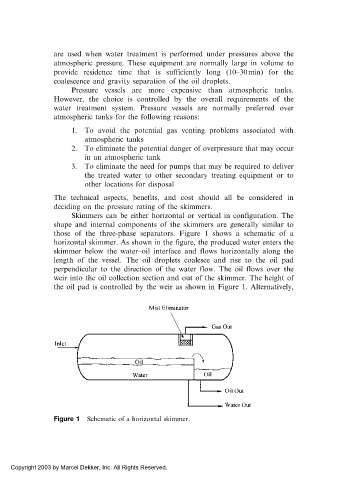
those of the three-phase separators. Figure 1 shows a schematic of a
horizontal skimmer. As shown in the figure, the produced water enters the
skimmer below the water–oil interface and flows horizontally along the
length of the vessel. The oil droplets coalesce and rise to the oil pad
perpendicular to the direction of the water flow. The oil flows over the
weir into the oil collection section and out of the skimmer. The height of
the oil pad is controlled by the weir as shown in Figure 1. Alternatively,
Figure 1 Schematic of a horizontal skimmer.
Copyright 2003 by Marcel Dekker, Inc. All Rights Reserved.