
Page 243 - Petroleum and Gas Field Processing
P. 243
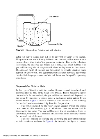
Figure 6  Dispersed gas flotation unit with eduction.


            cubic feet (SCF) ranges from 0.2 to 0.5 SCF/bbl of water to be treated.
            The gas-saturated water is recycled back into the unit, which operates at a
            pressure lower than that of the gas–water contactor. Due to the reduction
            in pressure, the dissolved gas breaks out of solution as small bubbles. The
            gas bubbles carry the oil droplets with them as they move to the surface.
            The size and depth of the unit are determined to provide retention times
            between 10 and 40 min. The equipment manufacturer normally determines
            the detailed design parameters of the unit based on the specific operating
            conditions.


            Dispersed Gas Flotation Units

            In this type of flotation unit, the gas bubbles are created, introduced, and
            dispersed into the bulk of the water to be treated. This is basically done by
            two methods. In one method, the gas bubbles are created and dispersed in
            the water by inducing a vortex using a mechanical rotor driven by an
            electric motor. Figure 7 shows a schematic cross section of a unit utilizing
            this method and manufactured by Petrolite Corporation.
                 The vortex induced by the rotor creates vacuum within the vortex
            tube. Due to this vacuum, gas is withdrawn into the vortex and is
            dispersed in the water. The gas bubbles carry the oil droplets as froth to
            the surface, where the oil is skimmed and collected in the recovery channel
            for removal out of the unit.
                 The other method of creating and dispersing the gas bubbles utilizes
            an inductor device as shown in Figure 8. As shown in the figure, a portion


 Copyright 2003 by Marcel Dekker, Inc. All Rights Reserved.