
Page 105 - Phase Space Optics Fundamentals and Applications
P. 105
86 Chapter Three
P input P out
L 1 L 2 L 1
Z Z
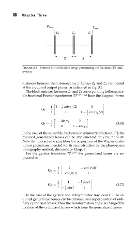
FIGURE 3.6 Scheme for the flexible setup performing the fractional FT and
gyrator.
distances between them denoted by z. Lenses L 1 and L 3 are located
at the input and output planes, as indicated in Fig. 3.6.
The block matrices for lenses L 1 and L 2 corresponding to the separa-
U f ( x , y )
ble fractional Fourier transformer R have the diagonal forms
1
1 1 − 2 cot( x /2) 0
G 1 = 1
z 0 1 − cot( y /2)
2
2 1 − sin x 0
G 2 = (3.76)
z 0 1 − sin y
In the case of the separable fractional or symmetric fractional FT, the
required generalized lenses can be implemented only by the SLM.
Note that this scheme simplifies the acquisition of the Wigner distri-
bution projections, needed for its reconstruction by the phase-space
tomography method, discussed in Chap. 4.
U g (ϑ)
For the gyrator transform R the generalized lenses are ex-
pressed as
1 1 − cot(ϑ/2)
G 1 =
z − cot(ϑ/2) 1
1
2 1 − sin ϑ
2
G 2 = (3.77)
1
z − sin ϑ 1
2
In the case of the gyrator and antisymmetric fractional FT, the re-
quired generalized lenses can be obtained as a superposition of ordi-
nary cylindrical lenses. Then the transformation angle is changed by
rotation of the cylindrical lenses which form the generalized lenses.