
Page 129 - Phase Space Optics Fundamentals and Applications
P. 129
110 Chapter Four
x θ
R (x , θ)
g θ
y θ y g(x, y)
x θ
θ x
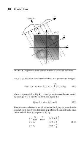
FIGURE 4.1 Projection scheme for the definition of the Radon transform.
say, g(x, y), its Radon transform is defined as a generalized marginal
+∞
R {g (x, y) ,x , } = R g (x , ) = g (x, y) dy (4.8)
−∞
where, as presented in Fig. 4.1, x and y are the coordinates rotated
by an angle . It is easy to see from this figure that
R g (x , + ) = R g (−x , ) (4.9)
Thus, the reduced domain ∈ (0, ) is used for R g (x , ). Note that the
integration in the above definition is performed along straight lines
characterized, for a given pair (x , ), by
x x
y = − for = 0,
sin tan 2
x = x for = 0 (4.10)
y = x for =
2