
Page 305 - Phase Space Optics Fundamentals and Applications
P. 305
286 Chapter Nine
Grating Fresnel images Self-images
Incident
plane wave
z
d
M
z T
N
1 z
2 T 2d 2
z T λ
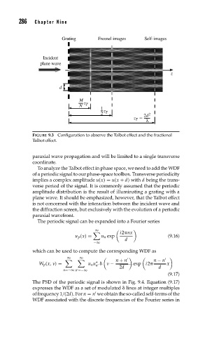
FIGURE 9.3 Configuration to observe the Talbot effect and the fractional
Talbot effect.
paraxial wave propagation and will be limited to a single transverse
coordinate.
To analyze the Talbot effect in phase space, we need to add the WDF
of a periodic signal to our phase-space toolbox. Transverse periodicity
implies a complex amplitude u(x) = u(x + d) with d being the trans-
verse period of the signal. It is commonly assumed that the periodic
amplitude distribution is the result of illuminating a grating with a
plane wave. It should be emphasized, however, that the Talbot effect
is not concerned with the interaction between the incident wave and
the diffraction screen, but exclusively with the evolution of a periodic
paraxial wavefront.
The periodic signal can be expanded into a Fourier series
∞
, i2 nx
u p (x) = u n exp (9.16)
d
−∞
which can be used to compute the corresponding WDF as
∞ ∞
, , n + n n − n
∗ exp i2
W p (x, ) = u n u − x
n
2d d
n=−∞ n =−∞
(9.17)
The PSD of the periodic signal is shown in Fig. 9.4. Equation (9.17)
expresses the WDF as a set of modulated lines at integer multiples
of frequency 1/(2d). For n = n we obtain the so-called self-terms of the
WDF associated with the discrete frequencies of the Fourier series in